
《1. Introduction》
1. Introduction
Total hip arthroplasty (THA) is an effective method for the treatment of end-stage hip joint disease. Even in successful surgeries, some patients still require hip revision procedures for various reasons. In the United States, 40 800 hip revision procedures were performed in 2005—a number that is expected to increase to 96 700 by 2030 [1]. Currently, more than half of hip revision procedures involve acetabulum revision [2]. A study on the French population shows that loosening is more common at the acetabular cup than at the femoral stem [3]. Acetabular cup loosening is usually accompanied by bone defects, which must be filled during surgical revision [4]. Acetabular bone defects are mainly caused by dissolved bone, stress shelter, and/or shifting of the prosthesis. The processing results directly affect the stability and long-term effect of prosthesis reconstruction. At present, the commonly used acetabular bone defect classification systems are the American Academy of Orthopedic Surgeons (AAOS) classification and the Paprosky classification [4,5]. However, these classifications cannot cover all of the acetabular bone defects—especially certain complex and large types for which the classification systems do not provide valuable guidance.
In the process of hip revision, bone integration of an acetabular prosthesis requires two conditions. First, the prosthesis should have good initial stability, because excessive micromotion prevents osseointegration at the bone-implant interface [6]; the micromotion should be less than 50 μm. A micromotion of 150 μm leads to bone absorption and fibrous tissue growth, eventually causing prosthetic loosening [7,8]. Second, there should be an adequate contact area between the prosthesis and the bone. At least 50% of the surface area of the component should be in contact with the host bone for potential ingrowth and to provide good mechanical support [9]. However, when the bone defect is serious and the structural support of the acetabulum is destroyed or even completely ruptured, an acetabular prosthesis test can only achieve a part or none of the initial stability. In such cases, although the use of a steel plate to fix the anterior and posterior columns of the acetabulum or the use of an acetabular reinforcement ring plus a bone graft is possible [10,11], the ultimate outcome still depends on the healing of the ruptured pelvis. If healing is not achieved, all internal fixation can only provide temporary support. Therefore, more reliable and effective solutions are needed to achieve good reconstruction for large acetabular bone defects.
Our department has performed a significant amount of work in the reconstruction of complex and large acetabular bone defects. It was previously reported that a personalized acetabular cup combined with a three-dimensional (3D)-printed bone-filling block could better realize the reconstruction of large acetabular defects in THA [12]. However, such reconstruction is still limited to manufacturing a prosthesis. Even if a computer can be used to design a good prosthetic fitting for the complicated appearance and mechanical structure of a bone defect, prosthesis production using traditional prosthetic technology is difficult to achieve. To solve this problem, based on the prophase work, we aimed at using 3D printing technology for bone defect evaluation, reconstruction prosthesis design and manufacture, and accurate intraoperative prosthesis installation.
《2. Materials and methods》
2. Materials and methods
《2.1. Patient history》
2.1. Patient history
This study was carried out after approval was granted by the Shanghai Ninth People’s Hospital Ethics Committee. Three patients with complex and large acetabular bone defects after THA were enrolled in our hospital from January 2016 to December 2016. The three patients are identified in this study as A, B, and C.
Patient A is a male aged 47 years. In 1996, he underwent bilateral THA due to ankylosing spondylitis. Postoperative recovery was satisfactory, but a progressive limp had developed in recent years. In 2005, he underwent symptomatic treatment using an embracing fixator for a fracture around the prosthesis in his left leg, which resulted from an accidental fall. However, his left hip symptom was still evident, with aggravating discomfort when walking.
Patient B is a male aged 63 years. In 1980, he underwent right THA because of a hip suppurative infection. The joint function was still limited, with an aggravated limp after the surgery. The revision surgery was not very successful. He experienced hip pain and severe limping again one year after the surgery. The lower limb was 6 cm shorter than the healthy side.
Patient C is a female aged 56 years. In 1981, she underwent left THA due to congenital hip dysplasia. However, the surgery failed. Two revision surgeries were performed in 1982 and 1987, but the lower limb was still severely shortened. Her symptoms have rapidly deteriorated since 2015. The left lower limb was 10 cm shorter than the healthy side.
《2.2. Prosthetic design and manufacture》
2.2. Prosthetic design and manufacture
In patient A, part of the bone defect was on the superior border of the bilateral acetabulum, while significant osteolysis was found from the right acetabulum to subregion I of the pelvis in patient B and from the left acetabulum to subregion I of the pelvis in patient C. The center of the acetabular prosthesis was designed 1.5 cm in patient A, 4 cm in patient B, and 6 cm in patient C below the original level of the acetabular center. One iliac wing fixator was used to reconstruct the acetabulum and fill the osteolytic region. Fixed screws were used to stabilize the prosthesis at the posterior superior iliac spine, ala ossis ilium, and pubis in patient A; at the posterior superior iliac spine, ala ossis ilium, pubis, and ischium in patient B; and at the posterior superior iliac spine in patient C. The obturator hook was designed to increase prosthesis stability. The bone interface was also designed as a porous structure to promote bone ingrowth.
The prosthesis design was completed using the Siemens NX software (version 11.0, Siemens, Gernamy). The prosthesis was manufactured using an EBM A1 3D printer (Arcam, Sweden). The specific method was as follows: ① The computed tomography (CT; thickness ≤ 1.5 mm) and X-ray data of the patient were acquired. The CT data were imported into the E-3D Medical software. After removing artifacts and checking with X-ray, a 3D model of the pelvis was reconstructed. ② The model was further imported into Siemens NX software in the form of a stereolithography (STL) file, and the sagittal, coronal, and horizontal planes of the pelvis were established. According to the contralateral acetabulum, the rotation center, anteversion, and abduction angles of the acetabulum cup were determined. ③ To optimize the mechanical properties of the pelvis, the structure of augments, the direction and length of fixing screws, and the position of fixing plates were designed. After further discussion on the fixation method and the range of porous area, the final structure of the prosthesis was determined and exported in the form of an STL file. ④ Before manufacturing the prosthesis, the STL file was further imported into the Magics software (appMagics Tech Co., Ltd., China) for final revision. The solid area and porous area were divided, and the wrong, overlapping, and redundant structural areas were removed. ⑤ Using an Arcam EBM A1 3D printer, the metal prostheses were printed according to its standard protocol. The process took about 24 h. After cooling for 6 h, removing the printing supports, trimming, polishing, screw thread making, sandblasting, and cleaning, the manufacture of the prosthesis was finally completed.
《2.3. Surgical process》
2.3. Surgical process
The surgical approach and incision for each patient were basically the same. However, the length of the incision and the extent of exposure differed due to different defect sizes and displacement of the prosthesis. During surgery, the failed prosthesis, false membrane, and pathological bone around the prosthesis were removed. Modification of the form of the bone defect was performed according to the preoperative simulation on the 3D-printed polymer resin pelvic model to facilitate prosthetic installation.
《2.4. Postoperative recovery and prognosis evaluation》
2.4. Postoperative recovery and prognosis evaluation
All the three patients were required to undergo radiological examination at one week, three months, six months, and 12 months after the surgery to observe the position and stability of the prosthesis. During late follow-up, the Harris hip score was used to evaluate limb function changes from pre-surgery to post-surgery.
Comparisons between radiological data and design data were carried out by the Siemens NX software (version 11.0) to evaluate the precision of the 3D printing prosthesis. The pelvic radiograph image was input into the Siemens NX software to cover the design image. The position of the two images was adjusted to make the obturator and anterior superior spine overlap. The nonoverlapped part of the prosthesis was then marked and calculated. Finally, the overlap degree was determined to judge the installation accuracy of the prosthesis.
《3. Results》
3. Results
《3.1. Preoperative imaging examination》
3.1. Preoperative imaging examination
Preoperative X-ray and CT images of each patient are shown in Fig. 1. The details are as follows:
Patient A: The images indicated that his bilateral hip joint prostheses were both loosened, but his left side was relatively more serious. The periprosthetic femoral fracture was fixed with an embracing fixator. The acetabular bone defect, which involved the entire region II and one-third of region I, was mainly distributed on the back of the acetabulum.
Patient B: The images indicated that his right hip joint prostheses were loosened, with prosthesis dislocation. A large bone defect was noted around the acetabular prosthesis involving the entire region II, half of region I, and a small part of region III. His right pelvis almost lost the mechanical support structure.
Patient C: The images showed a significant loose shift of the left hip prosthesis. The acetabulum laterally dug out upward and was buried in the ilium. Large bone defects were found around the acetabular prosthesis involving the entire region II, most of region I, and part of region III, with severe deformation.
《Fig. 1》
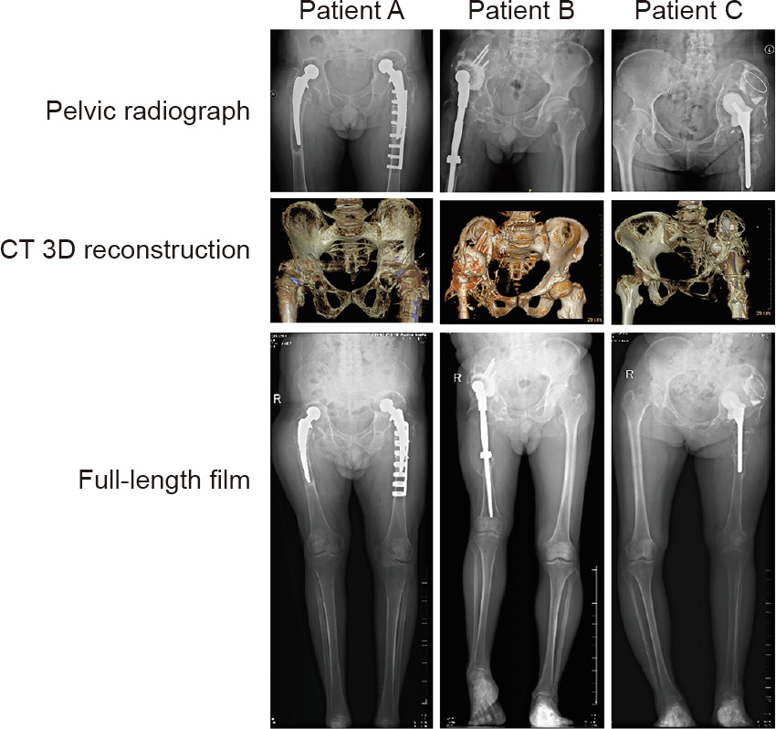
Fig. 1. Preoperative X-ray and CT examination. In patient A, the bilateral hip joint prostheses were both loosened. A periprosthetic femoral fracture was fixed with an embracing fixator on the left side. The acetabular bone defect mainly involved the entire region II and one-third of region I of the pelvis. In patient B, the right hip joint prostheses were loosened with prosthesis dislocation. A large bone defect was noted around the acetabular prosthesis involving the entire region II, half of region I, and a small part of region III. In patient C, X-ray and CT images showed a significant loose shift of the left hip prosthesis. The acetabulum laterally dug out upward and was buried in the ilium. Large bone defects were found around the acetabular prosthesis involving the entire region II, most of region I, and part of region III with severe deformation. R: right.
The acetabular bone defect volume of these three patients, measured by the Siemens NX software (version 11.0), is shown in Fig. 2. Among the three patients, the bone defect volume in all four hips was greater than 50 000 mm3 .
《Fig. 2》

Fig. 2. Calculation of bone defect volume. Detailed data were calculated using the Siemens NX software (version 11.0). The bone defect volumes of patient A were 51 697.49 mm3 on the right side and 85 568.04 mm3 on the left side. The bone defect volumes of patients B and C were 89 866.14 and 94 014.56 mm3 , respectively.
《3.2. Prosthesis design and computer simulation installation》
3.2. Prosthesis design and computer simulation installation
Fig. 3 shows key steps of the prosthesis design. For patient A, who had bilateral lesions, the two revision prostheses had a uniform design. Due to the loss of the normal position of the femoral head center and the severe contracture of soft tissue, his bilateral femoral head center was finally placed near and above the shifted center of the femoral head, which, in our opinion, would reduce surgical difficulty and guarantee maximum bilateral limb function. For patients B and C, who both had a unilateral lesion, the confirmation of the femoral head center mainly relied on the femoral head of their healthy side. However, it was difficult to achieve the same height on both sides of the femoral head center because of the severe contracture of soft tissue. On the premise of preventing neurovascular injury, we reduced the height of the femoral head center of the affected limb as much as possible. The position of the acetabular cup, which was composed of the integrated revision prosthesis with the defect filling prosthesis, was then determined according to the femoral head center. Figs. 3(f) and (g) show the porous structure design (red color) and nail track (black color). According to the design scheme, the prototype of the prosthesis was established and the simulation installation was carried out on a computer to preliminarily verify the match degree of the prosthesis (Fig. 4).
《Fig. 3》

Fig. 3. Standard design process of the integrated revision prosthesis. (a) Determining the femoral head center of the affected side; (b) designing the position of the acetabular cup according to the femoral head center; (c) the filling prosthesis for the large bone defect; (d, e) integrating the acetabular cup and bone defect-filling prosthesis to achieve the whole revision prosthesis; (f, g) the porous structure on the surface of the prosthesis (red color) and nail track (black color).
《Fig. 4》
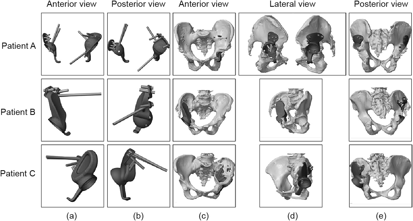
Fig. 4. Computer simulation installation of the prosthesis. (a, b) The simulation appearance of the revision prosthesis; (c–e) the prosthesis could completely match the bone defect and satisfy the position of the acetabular cup.
《3.3. Intraoperative view and prosthetic installation》
3.3. Intraoperative view and prosthetic installation
Figs. 5(d)–(f) show that all three patients (including all four diseased hip joints) have large, widely distributed wear particles around the prosthesis: ultra-high molecular polyethylene wear particles in patient A, black nano-metal particles in patient B, and ceramic particles in patient C. Distinctive porous structures can be seen on the surface of the prosthesis, which could be conducive to bone integration (Figs. 5(g)–(l)). Fixation and installation of the prostheses based on the related data from the computersimulated prosthetic installation are presented in Figs. 5(m)–(o).
《Fig. 5》
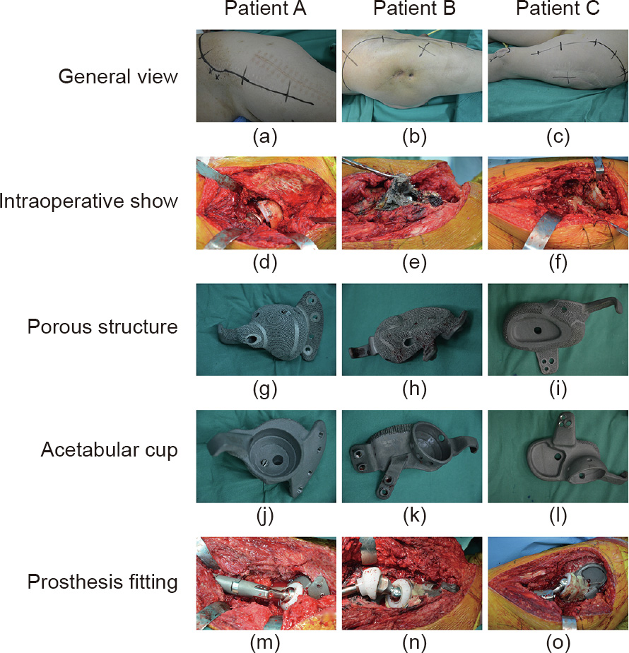
Fig. 5. Intraoperative view and prosthetic installation. (a–c) Selection of surgical incision; (d–f) intraoperative exposure of the damaged prosthesis; (g–i) porous structure on the prosthesis surface; (j–l) acetabular cup; (m–o) completion of the prosthetic installation.
《3.4. Postoperative recovery》
3.4. Postoperative recovery
All four prostheses implanted in the three patients achieved satisfactory stabilization. The Harris hip score for the four hip prostheses was obtained at three months, six months, and 12 months, postoperatively, and showed satisfactory results. The preoperative and postoperative scores are shown in Table 1.
《Table 1》
Table 1 Harris hip scores of the three patients.

Both sides of the lower limb achieved the basic isometric length after two operations in patient A. Because of the intricacy of the soft tissue near the implant, the right lower limb was lengthened by 3 cm in patient B. Patient C suffered severe limb shortening. Fearing permanent nerve injury, we lengthened the leg by approximately 6 cm.
All three patients could walk with the help of a brace six weeks after the surgery (Appendix A). Patient B could walk without any help three months after the surgery. Although patients A and C required the help of a brace, their range of motion had improved at six weeks. At six months after the surgery, all three patients could walk without any brace. Nevertheless, due to atrophy of the soft tissue around the hip, the same length on both sides could not be achieved. Thus, varying degrees of limp were noted in the three patients.
In radiographic assessment, we evaluated the X-ray image obtained at 12 months after the surgery and compared it with that at one week after the surgery. The implants in all three patients remained stable. We could not detect any loosened implants or osteolysis around the implants (Fig. 6). As shown in Fig. 7, the degree of prosthesis overlap between the radiographic images and the design images was at least 95% or more, indicating very good accuracy of the 3D-printed prosthesis.
《Fig. 6》

Fig. 6. X-ray examination to evaluate the stability of the revision prosthesis. A comparison of the X-ray image at one week with that at 12 months after the surgery showed that all the prostheses were stable at 12 months after the surgery and no obvious loosening could be observed.
《Fig. 7》
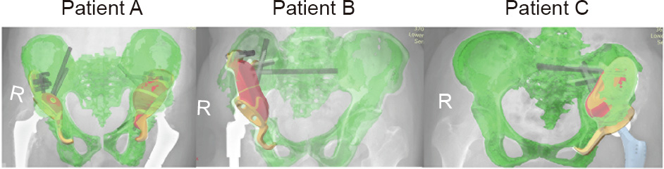
Fig. 7. Degree of prosthesis overlap. The degree of prosthesis overlap in the radiographic images and design images was at least 95% or more, indicating very good accuracy of the 3D-printed prosthesis. R: right.
《4. Discussion》
4. Discussion
The difficulty of surgical reconstruction of acetabular complex bone defects is directly affected by the extent and scope of osteolysis. When the structural support of the acetabulum is destroyed and the continuity of the pelvis is interrupted, the difficulty of reconstruction is greatly increased. Due to the wide range of osteolysis and the complexity of the geometry and mechanical properties in this type of bone defect, its reconstruction is difficult to realize, even with the application of a traditional, personalized, custom-made prosthesis. In recent years, with the rise and development of 3D printing technology, new approaches have been introduced to solve this problem [13–16]. 3D printing technology not only realizes the spatial structure design of the individual implant, but also achieves movement analysis and mechanical analysis of that implant. This technology is combined with computer software and hardware, medical imaging, and post-processing technology to build geometric modeling and finite-element modeling of the bone defects. Furthermore, the 3D printing technique can easily be used to design the self-movement constraint mechanisms of the prosthesis. For example, in this study, the designs of the fixed nail channel in the prosthesis, obturator hook, and porous structure of the bone integration interface greatly increased the stability of the reconstructed prosthesis and the effect of bone integration. The designs can compensate for the function of ligaments and other joint-stability structures, which would be removed in the surgery, and achieve a better balance between function and stability.
In this study, all three patients had large defects and little bone mass around the defects. Therefore, there was a risk of poor stability of the reconstructed prosthesis. To avoid the possibility of postoperative prosthesis loosening before the surgery, we focused on improving the precision reconstruction of the bone defect and the optimal design of the prosthesis during patient treatment. Based on our experience, we summarize the basic design principles of 3D-printed hip prostheses as follows: For accurate simulation of the bone defects, we routinely perform thin-slice spiral CT scans of the pelvis, input the Digital Imaging and Communications in Medicine (DICOM) data into the computer, and use Materialise’s interactive medical image control system (MIMICS, Materialise, Belgium) software to process the data. Reconstruction of the pelvis and defect can be realized in the computer. Based on the principle of matching the geometry and mechanical properties, combined with the original design of the obturator hook, the fabrication scheme of an individualized reconstruction prosthesis is established.
In terms of the optimization design of the implant bone contact interface, we found that a 3D-printed porous titanium alloy with a pore diameter of 300–400 μm is more favorable for tissue and cell growth [17]. Based on relevant data of the hard tissue section of a reconstructed specimen of goat bone defect [17] and our prophase clinical experience, a depth of 3 mm from the bone contact interface of the scaffold material might be the most appropriate depth for early bone ingrowth. Thus, when we designed the four prostheses in the three cases, the interface part with the bone was printed into a porous trabecular structure with a 300–400 lm aperture and a thickness of 3 mm to increase the stability and firmness of the prosthesis, which may be the first time this has been accomplished in a human prosthesis design.
3D printing technology provides a viable reconstruction method for complicated and large acetabular defects. Follow-up results indicate that excellent mechanical stability and significantly improved hip scores were achieved. However, additional cases need to be included to obtain more compelling data. Moreover, the complex and large pelvic bone defects classification put forward above will be more conducive to guiding 3D printing technology application and prosthesis design, which will be the focus of our next work.
《5. Conclusions》
5. Conclusions
3D printing is a very advantageous technology in the design and reconstruction of large and complex defects in the revision of THA. It is able to achieve good curative effects in such patients. As it develops, it is bound to further improve the prognosis of patients.
《Acknowledgements》
Acknowledgements
This work is supported by National Key Research and Development Program of China (2016YFC1100600), the National Natural Science Foundation of China (81972058 and 81902194), the Multicenter Clinical Research Project of Shanghai Jiao Tong University School of Medicine (DLY201506).
《Compliance with ethics guidelines》
Compliance with ethics guidelines
Yongqiang Hao, Lei Wang, Wenbo Jiang, Wen Wu, Songtao Ai, Lu Shen, Shuang Zhao, and Kerong Dai declare that they have no conflict of interest or financial conflicts to disclose.
《Appendix A. Supplementary data》
Appendix A. Supplementary data
Supplementary data to this article can be found online at https://doi.org/10.1016/j.eng.2020.04.013.


 京公网安备 11010502051620号


