
《1. Introduction》
1. Introduction
Biodegradable metallic materials have drawn extensive attention in recent years, especially for orthopedic applications, due to their excellent combination of biodegradability and mechanical properties [1–4]. Among them, Mg and its alloys, which have been acclaimed as revolutionizing biomaterials, have been widely investigated and clinically explored [4–6]. Their mechanical properties are similar to those of natural bone; hence, these substances could avoid the stress shield effect caused by a mismatch of elastic modulus [7,8]. In addition, Mg is the fourth most abundant element in the human body and is essential to human metabolism [9]. Furthermore, Mg ions have been found to be crucial to bone healing and formation [10,11]. However, the high degradation rate of pure Mg and some Mg-based alloys in the physiological environment has inhibited their further clinical applications [12]. A novel biodegradable Mg-based alloy developed by our group, namely Mg–Nd–Zn–Zr alloy (JDBM), surprisingly exhibits excellent corrosion resistance and antibacterial properties [13]. Long-term in vivo degradation studies of JDBM screws for mandibular fracture and JDBM cardiovascular stents have been conducted, and the experimental results have verified their potential for medical implantation [14,15]. However, these reported Mg-based implants were mainly fabricated through conventional manufacturing processes, whose limitations in the production of complex geometries and desirable mechanical properties result in non-negligible disadvantages for patient-specific implants or tissue engineering scaffolds.
Lately, additive manufacturing (AM) techniques have gained a great deal of attraction due to their superiority over conventional manufacturing processes in the precise control of complex or porous architectures, and have emerged as promising methods for the fabrication of metallic biomaterials [16,17]. Conventional or specific metallic implants, such as Ti [18,19] or stainless steel [20,21], have been additively manufactured and experimentally analyzed. However, the AM of biodegradable Mg has been more challenging due to the difficulty of preparing Mg powders and their flammability. Recently, selective laser melting (SLM)-processed Mg has been fabricated and investigated, revealing promising applications in the future medical market [22–26]. In particular, a WE43 scaffold with a diamond structure was fabricated using SLM for the first time and met the functional requirements for bone substitutes [27,28]. However, a bare WE43 scaffold was found to be unsuitable for cell adhesion, and the architecture of porous Mg also needs improvement.
The present work first analyzes the challenges presented by the AM of biodegradable Mg alloys. Next, it introduces solutions to meet these challenges, including AM parameter optimization and the fabrication of AM-processed JDBM scaffolds with preferable structures using SLM. It also reports on our investigation of the further surface treatment of AM-processed scaffolds.
《2. Challenges in the AM of biodegradable Mg alloys》
2. Challenges in the AM of biodegradable Mg alloys
Due to the inherent properties of Mg alloys, which include a low vapor temperature, a high vapor pressure, and a high tendency to oxidize [29], the AM of biodegradable Mg-based implants presents some challenges.
《2.1. Difficulty in powder preparation》
2.1. Difficulty in powder preparation
The production of Mg powders is very dangerous due to their high tendency to explode, and few enterprises are engaged in the preparation of these powders. Nowadays, only pure Mg, AZ91D powders, and WE43 powders are available on the market. Since elemental Al has biological toxicity and the AZ91D alloy contains 9 wt% Al, only pure Mg and WE43 powders are currently used for the AM of biodegradable Mg-based implants.
The basic methods for the production of Mg powders include mechanical crushing, the atomization of molten metal, evaporation–condensation, and electrolysis [30]. The powder size that is suitable for the AM of biodegradable metallic implants is in the range of 20–70 μm, and most such powders are produced by the gas atomization process [24,25]. However, the Mg powders produced by inert gas atomization have a particle size ranging from several microns up to 0.5–1.0 mm, which makes the utilization rate of the useable powders very low.
《2.2. Powder splash》
2.2. Powder splash
Serious powder splash can be observed during the AM process of Mg alloys, caused by the low vapor temperature and high vapor pressure of these alloys. This phenomenon is quite different from the AM processes of steel, Ti, or Al alloys, and significantly reduces the stability of the AM production of Mg alloys. Since some Mg powders along the scanning path are removed by the vapor, defects are likely to generate during the subsequent scanning track. Therefore, a powder-supplement strategy must be implemented during the AM process of Mg alloys. However, there is as yet no relevant research about the interaction between the vapor of Mg powders, gas flow, and laser input. Decreasing the vapor trend of Mg powders would be another possible solution. Zumdick et al. [24] successfully fabricated WE43 cubes using a very low energy input; in their method, the build plane was slightly shifted from the laser beam’s focal plane to generate a beam size of approximately 125 μm—larger than the original beam size of about 90 μm. In this way, the energy input for the fabrication of WE43 cubes was reduced by a factor of two.
《2.3. Cracks》
2.3. Cracks
Unfortunately, cracks occasionally appear during the AM fabrication of Mg cubes. The reason for crack formation still remains unclear, but is probably related to the powder splash because the crack tendency decreases with a decrease in powder splash under a lower energy input. Fig. 1 shows the typical cracks that form during the SLM process of a Mg–15Gd–1Zn–Zr alloy (GZ151K).
《Fig. 1》

Fig. 1. Cracks observed during the AM of GZ151K. (a) Tensile specimens, with cracks generated vertical to the building direction; (b) optical micrograph (OM) image of the cracks on the YZ plane in part (a).
《3. Solutions and research progress in the AM of biodegradable Mg alloys at Shanghai Jiao Tong University》
3. Solutions and research progress in the AM of biodegradable Mg alloys at Shanghai Jiao Tong University
Due to the complex physics mechanisms during the SLM process and the intrinsic properties of Mg alloys, the two major variables in the adjustment of the SLM process—namely, the process-related parameters and feedstock-related parameters— must be chosen carefully. For the production of Mg powders (i.e., feedstock-related parameters), the oxygen content must be kept as low as possible due to the powders’ high tendency toward oxygenation, even in ultra-high-purity Ar gas [31]. Meanwhile, the atomization techniques used in the fabrication of other metallic powders should be developed for Mg powders in order to allow the acquisition of a suitable powder size [32]. The main goal of the fabrication of SLM-processed Mg is to achieve high density and avoid potential defects, and the most common method is through the alteration of the process-related parameters (i.e., laser power, scan speed, hatch spacing, etc.) [33]. Powder splash can be reduced by increasing the laser scan speed or decreasing the laser power [34]. Moreover, the chemical composition of the Mg alloys should be appropriately selected based on their different susceptibility to cracking [35]. The initial temperature of the substrate should also be elevated in order to narrow the temperature gradient between the substrate and the metallic powders, thus further avoiding the formation of hot cracks. By comprehensively taking the above-mentioned factors into consideration, we managed to fabricate AM-processed Mg alloys. The related progress is presented in the following sections.
《3.1. Preparation of JDBM powder》
3.1. Preparation of JDBM powder
Shanghai Jiao Tong University (SJTU), in cooperation with Tangshan Weihao Magnesium Power Co., Ltd., produced several kinds of Mg powders for AM using the gas atomization process, including GZ151K and JDBM alloys. Fig. 2 shows scanning electron microscope (SEM) images of the sieved JDBM powder, which has a particle size in the range of 50–75 μm. As shown in the figure, most of the powder particles have a smooth surface and good roundness. It is also observable that smaller particles are attached onto the surface of some powder particles (indicated by white arrows in Fig. 2(a)), and that some powder particles have a partial shell (indicated by black arrows in Fig. 2(a)). A corresponding magnified SEM image of the JDBM powder (Fig. 2(b)) shows that a fine network of secondary phases can be observed on the surface.
《Fig. 2》
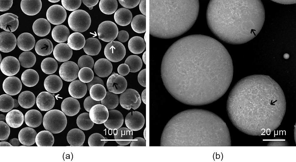
Fig. 2. (a) SEM image and (b) corresponding magnified image of gas-atomized JDBM powder.
《3.2. Optimization of AM parameters》
3.2. Optimization of AM parameters
As stated above, powder splashing and cracking may occur during the AM fabrication process of Mg alloys. To optimize the process parameters, the effects of laser power (P, W), scan speed (V, mm·s-1 ), and hatch spacing (HS, mm) on the microstructure of GZ151K cubes were studied. The relationship between the specific energy input (ψ = P/(HS·V·t)), where t is the layer thickness (t = 30 μm), and the density of AM samples was evaluated; the results are shown in Fig. 3. It can be seen that the density increases with the increment of specific energy input and stabilizes at the level of 2 g·mm-3 , and a higher density corresponds to fewer defects and better mechanical properties. The optimized process parameters for the JDBM alloy are listed in Table 1.
《Fig. 3》
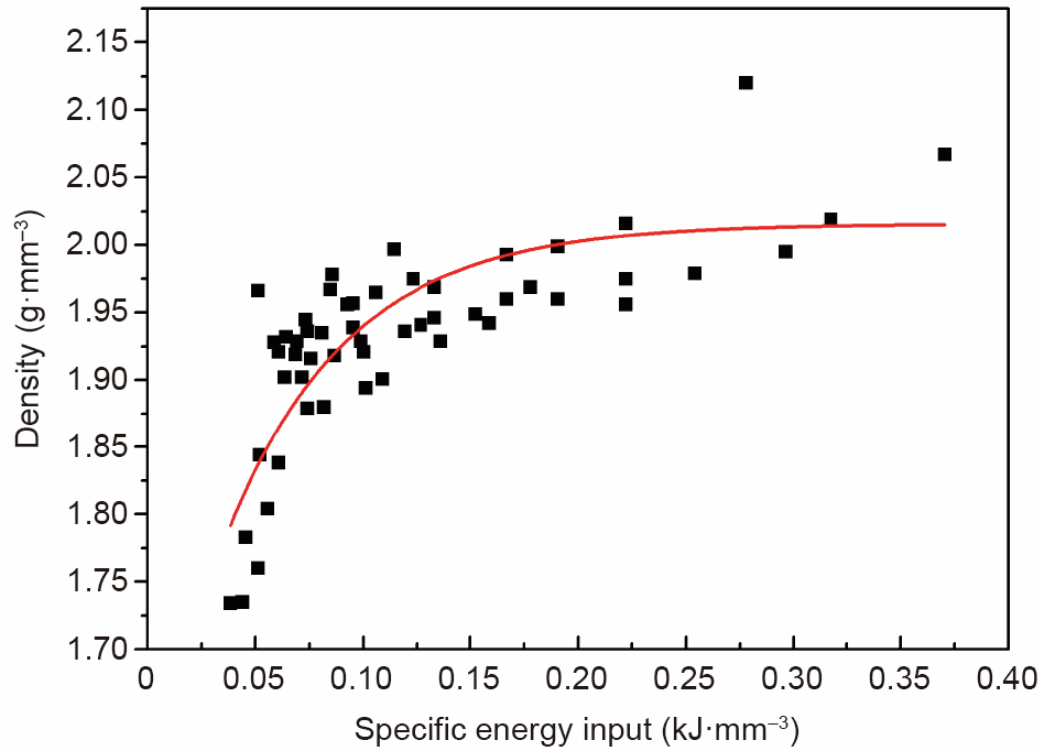
Fig. 3. Exponential decay fitting of the apparent density (ρ)–specific energy input (ψ) of AM-processed GZ151K samples, where ρ = –0.44exp (–17.54ψ) + 2.02, and ψ = P/(HS·V·t), R2 = 0.9995.
《Table 1》
Table 1 Optimized AM fabrication parameters.

《3.3. Design and fabrication of JDBM scaffolds》
3.3. Design and fabrication of JDBM scaffolds
Three different architectures—namely, biomimetic (B), diamond (D), and gyroid (G)—were designed using Rhinoceros® 6.0 software. The B scaffold has a random structure mimicking that of natural bone, the D scaffold is a topologically ordered structure with a beam lattice, and the G scaffold has triply periodic minimal surface (TPMS) structures with zero mean curvature. All as-designed scaffolds possessed the same porosity of 75% and average pore size of 800 μm, and were fabricated using gas-atomized JDBM powder under optimized process parameters. Specimens with a diameter of 10 mm and a height of 12 mm were manufactured using an SLM machine under the condition of an oxygen content below 100 parts per million (ppm). After fabrication, all specimens were polished by an electrochemical polishing station with electrolyte consisting of 10 vol% perchloric acid and 90 vol% C2H5OH. The architectures of the as-polished specimens were analyzed by micro-computed tomography (micro-CT) with a resolution of 17 μm. The micro-CT-reconstructed structures, the computeraided design (CAD) design models, and macrographs of the aspolished specimens are presented in Fig. 4. The micro-CT results suggest that the as-polished scaffolds have fully interconnected structures consistent with the as-designed models.
《Fig. 4》
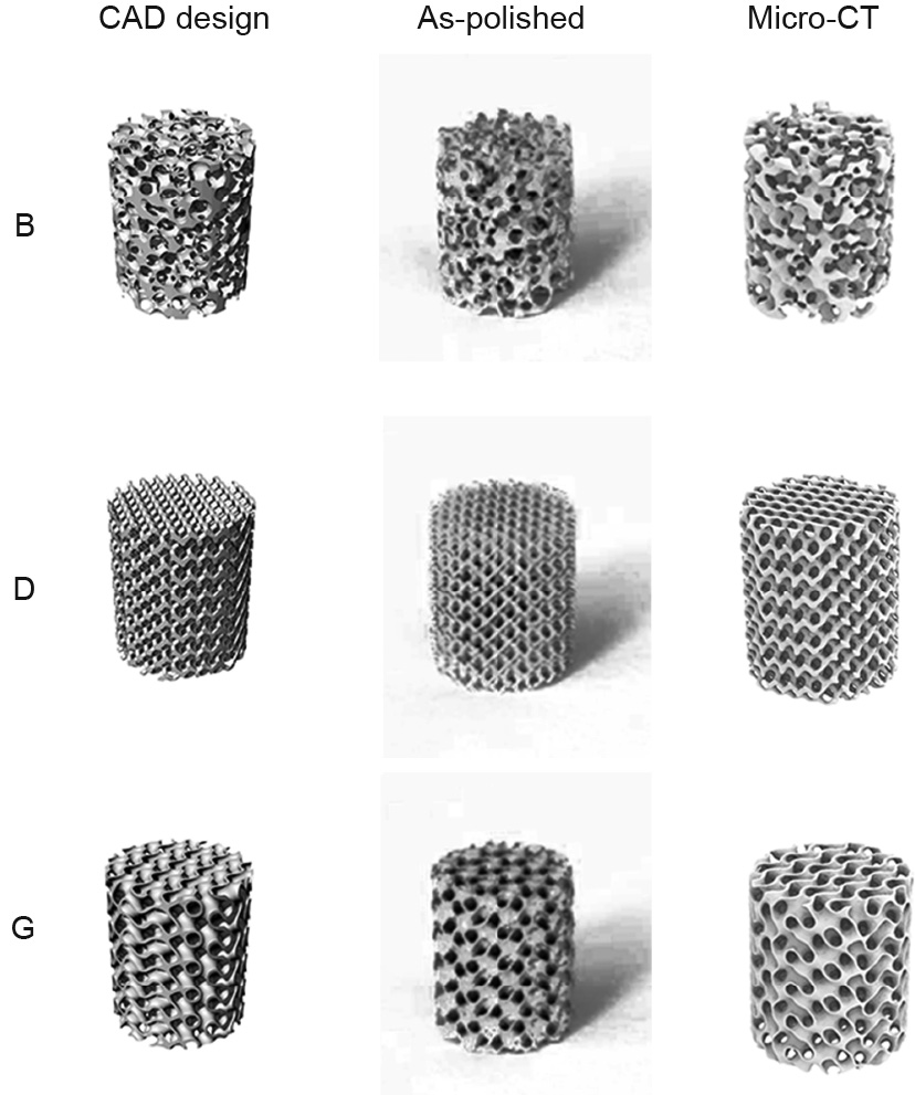
Fig. 4. CAD design models and as-polished architectures of three different scaffolds: biomimetic (B), diamond (D), and gyroid (G).
Fig. 5 shows cross-sections from the micro-CT images and SEM images of the as-polished specimens. It is clear that the surfaces of the as-polished porous structures are smooth, no unmelted powder particles remain, and no cracks can be observed. Therefore, the AM-processed JDBM scaffolds satisfy the requirements for tissue engineering: namely, high porosity and a fully interconnected cellular structure [36].
《Fig. 5》
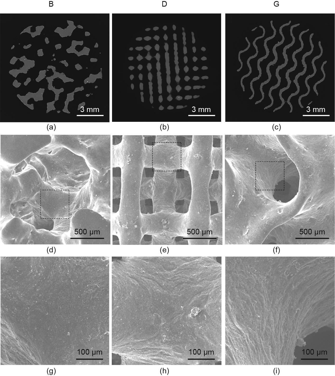
Fig. 5. (a–c) Micro-CT images, (d–f) SEM images, and (g–i) corresponding magnified images of the as-polished B (a, d, g), D (b, e, h), and G (c, f, i) scaffolds.
《3.4. Mechanical performance and in vitro degradation behavior of JDBM scaffolds》
3.4. Mechanical performance and in vitro degradation behavior of JDBM scaffolds
Compression tests were conducted using a Zwick AG-100KN testing machine (ZwickRoell, Germany) at room temperature. The as-polished scaffolds, with a diameter of 10 mm and a height of 12 mm, were compressed under displacement control with a crosshead speed of 1 mm·min-1 , and the stress–strain curves were recorded in terms of engineering stress and strain. Three replicates were tested for each kind of scaffold. The Young’s modulus of the scaffolds was determined by the slope of the initial linear part of the stress–strain curves. The yield strength was calculated by the 0.2% offset method, and the plateau strength was obtained at the strain value of 30%. Fig. 6 shows the compressive stress–strain curves of the as-polished scaffolds. All curves show similar compressive characteristics despite the different structures. The curves exhibit three typical stages of porous structures [37]: the elastic stage (I), long plateau stage (II), and densification stage (III). It is evident that the stress–strain curves of the D and G scaffolds display stress fluctuations during the long plateau stage, and the peak stress barely increases until the densification stage; however, the stress–strain curve of the B scaffold shows more strain hardening than stress fluctuations in stage II, which indicates that the mechanical responses of the AM specimens depend heavily on their unique structures.
《Fig. 6》
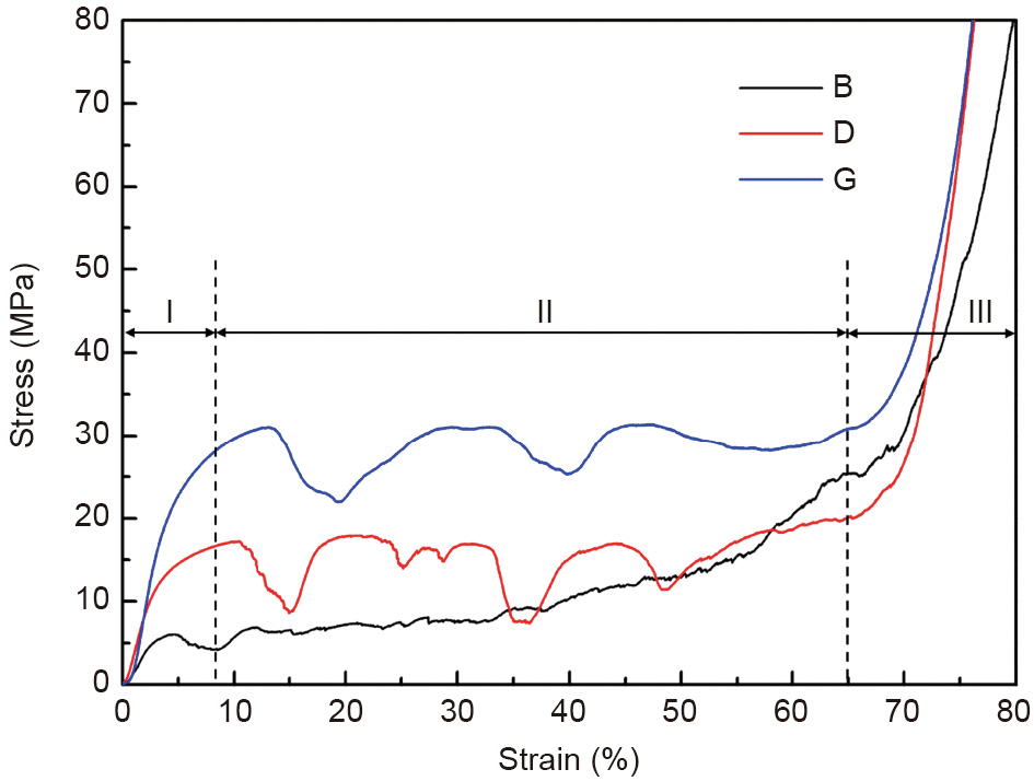
Fig. 6. Compressive stress–strain curves of as-polished B, D, and G scaffolds.
The relatively low mechanical strength of the B scaffold can be attributed to the higher failure tendency of its partly thin strut, as shown in Fig. 5(a), in comparison with the topologically ordered structures (D and G scaffolds) with uniform structure thickness. It was found that the sheet-based G scaffold exhibited a stretching-dominated behavior under compression load, resulting in a higher mechanical strength than the strut-based D scaffold, which exhibited bending-dominated compression behavior [38]. The fluctuations of the stress–strain curves were a consequence of the structure and material. The stress–stain curves of the D and G scaffolds showed more obvious fluctuations than that of the B scaffold, probably due to the uniformly distributed unit cell of the former two scaffolds along the compression direction and the related compressive deformation layer by layer. However, the number of unit cells for the D scaffold is greater than that of the G scaffold, even though both scaffolds have the same average pore size, which results in different humps in the long plateau stage. Meanwhile, the shear deformation mode of the Mg material at room temperature due to its intrinsic hexagonal close packed (HCP) structure also contributes to the fluctuations in the stress– strain curves.
The corresponding mechanical properties are summarized in Table 2. It is apparent that the G scaffold has the best mechanical properties, with a plateau stress of (32.34 ± 1.36) MPa and a Young’s modulus of (0.760 ± 0.020) GPa, while the B scaffold has the worst mechanical performance. Despite the different compressive performances of the three scaffolds, their mechanical properties are in the range of cancellous bone strength, whose compressive strength and Young’s modulus are 0.2–80.0 MPa and 0.01–2.00 GPa, respectively [39]; this validates the medical potential of the AM-processed JDBM scaffolds for tissue engineering.
《Table 2》
Table 2 Mechanical properties of the B, D, and G scaffolds.

To characterize the degradability of the AM-processed JDBM scaffolds, disk-like specimens with a diameter of 10 mm and a thickness of 3 mm were prepared. All specimens were immersed in 3 mL of Dulbecco’s modified eagle medium (DMEM; Gibco, USA) supplemented with 10% fetal bovine serum (FBS; Gibco, USA) and 1% penicillin and streptomycin (Gibco, USA) at 37 °C with 5% CO2, and the medium was refreshed every 2 or 3 d [40]. The evolution of the extracts of the JDBM scaffolds is shown in Fig. 7. It can be seen that the Mg2+ concentration increased rapidly in the first 3 d for all scaffolds, while the D scaffold exhibited a higher Mg2+ concentration than the other two scaffolds. At Day 7, the Mg2+ concentration of the D scaffold started to decrease to about 1300 ppm—a level similar to those of the B and G scaffolds. The Ca2+ concentration of all samples decreased extensively after immersion for 6 h, and became comparatively stable in the following days, although the Ca2+ concentration of the D scaffold was the lowest during the immersion time. In addition, the increase in pH reached a peak at Day 3 for all scaffolds, and decreased tremendously at Day 7. The increase in osmolality rose gradually during the 7 d for all specimens, and reached a similar level at Day 7.
《Fig. 7》
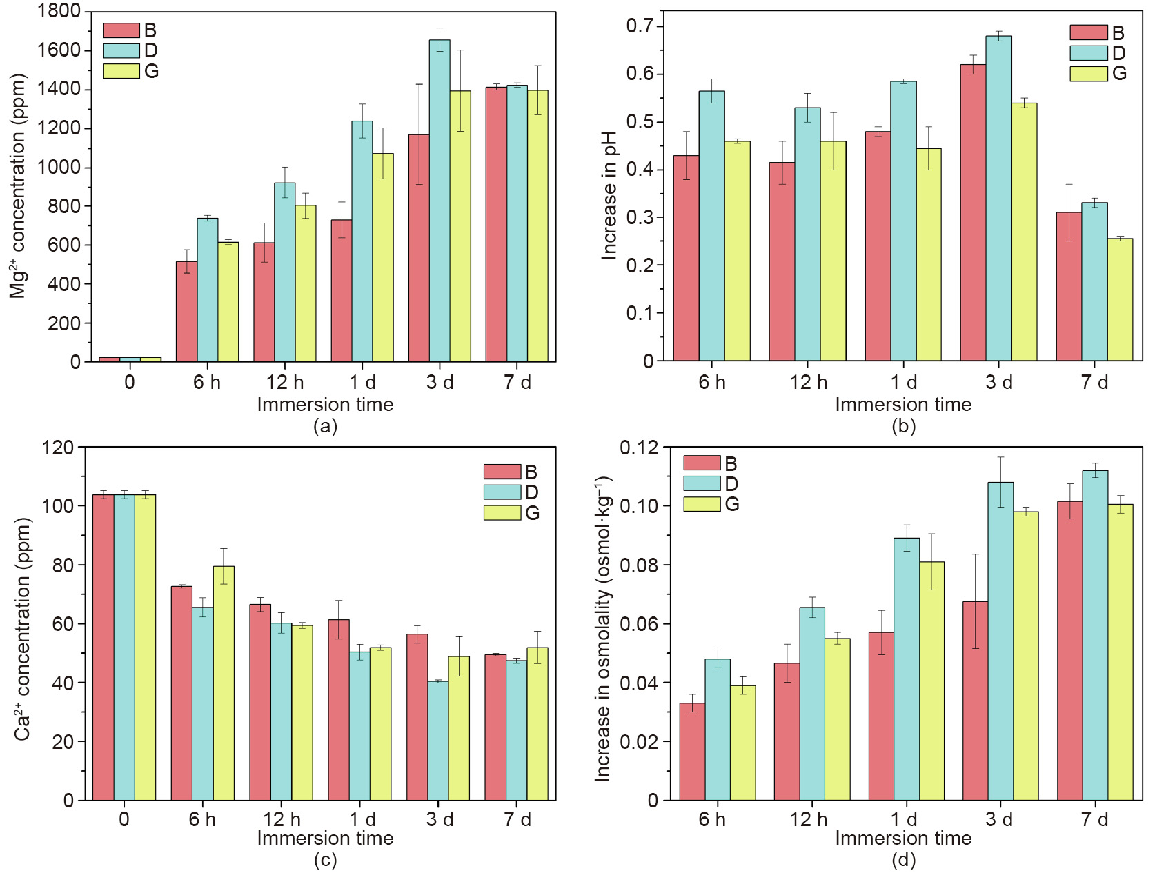
Fig. 7. (a) Mg2+ concentration, (b) increase in pH, (c) Ca2+ concentration, and (d) increase in osmolality of the extracts of the JDBM scaffolds.
Jia et al. [40] found that the sharp increase in the Mg2+ concentration of the scaffolds occurred because of the large surface of the porous structures that was in contact with the corrosive medium; the decrease in the Ca2+ concentration in the extracts was due to the deposition of calcium phosphate onto the surface as a result of the alkaline environment caused by the increase in pH. It can be seen that the D scaffold displayed more severe corrosion behavior than the other two scaffolds in the first 3 d, although the disparities narrowed at Day 7 to reach a similar level, indicating better clinical application prospects of the B and G scaffolds.
《3.5. Surface treatment of the G scaffold》
3.5. Surface treatment of the G scaffold
To improve the corrosion resistance and biocompatibility of the AM-processed JDBM scaffold, the G scaffold, which had the best combination of mechanical performance and degradation behavior, was selected and modified with a dicalcium phosphate dihydrate (DCPD) coating by immersing it in a mixed solution of NaNO3, Ca(H2PO4)2·H2O, and H2O2 for 12 h, as described before [41]. The detailed chemical composition of the solution is listed in Table 3. The porosities of the uncoated and coated scaffolds were measured by the Archimedes method. The in vitro degradation behavior and cell adhesion of the coated scaffold were examined through an immersion test and a cell culture assay.
《Table 3》
Table 3 Chemical concentration of the solution for DCPD treatment.
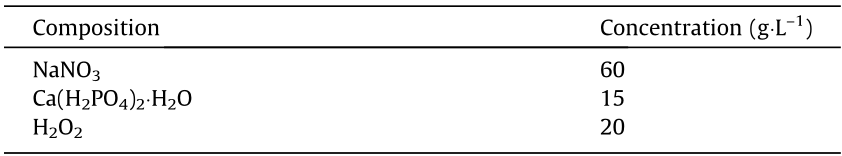
Fig. 8(a) shows macrographs of the G structure before and after DCPD treatment, denoted as G and G-DCPD, respectively. Figs. 8(b) and (c) respectively show the SEM image of the GDCPD scaffold and the corresponding magnified image. It is clear that the DCPD coating formed uniformly on the surface and has a crystalline-like microstructure. The G-DCPD scaffold still remains as a G structure, in spite of the decrease in porosity due to the increase in thickness after the DCPD coating, as indicated by Fig. 8(d).
《Fig. 8》
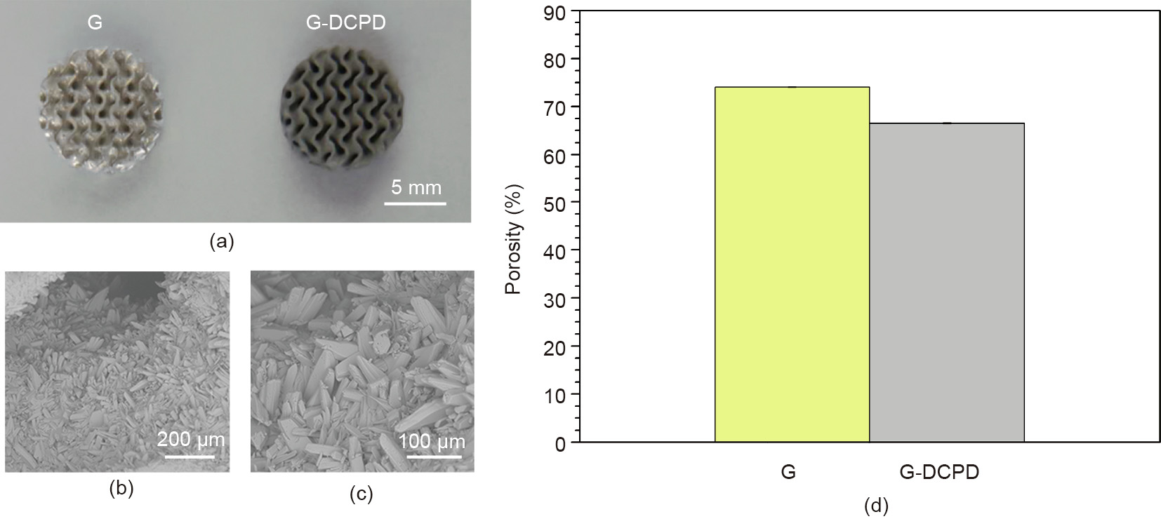
Fig. 8. (a) Macrograph, (b–c) SEM, and (d) porosity of the G-DCPD scaffold.
Fig. 9 shows the change in the Mg2+ and Ca2+ concentration, pH, and osmolality of the G-DCPD scaffold extracts compared with those of the G scaffold, as mentioned above. It is evident that the Mg2+ concentration of the G-DCPD scaffold is significantly lower than that of the G scaffold during the immersion time; a similar result was found in terms of the increase in osmolality. Although the increase in the pH of the G-DCPD scaffold was also lower in the first 3 d, the values became close due to the downtrend of the increase in the pH of the G scaffold. In contrast, the Ca2+ concentration of the G-DCPD scaffold was significantly higher than that of the G scaffold during the immersion test. It can be concluded that the G-DCPD scaffold has a lower in vitro degradation rate than the G scaffold. Niu et al. [41] have demonstrated that CaHPO4·2H2O is deposited on the surface and combined tightly with the JDBM substrate after DCPD treatment; it acts as a block layer between the Mg substrate and the corrosion medium, thus improving the corrosion resistance of the coated scaffolds.
《Fig. 9》
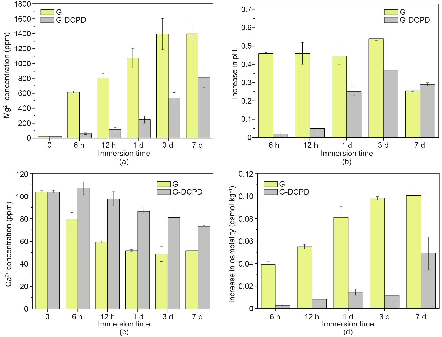
Fig. 9. (a) Mg2+ concentration, (b) increase in pH, (c) Ca2+ concentration, and (d) increase in osmolality of the extracts of the G and G-DCPD scaffolds.
For the cell adhesion tests, the scaffolds were seeded with 1 × 10⁵ MC3T3-E1 cells in a 12-well plate and incubated in 3 mL of α-modified Eagle’s medium (α-MEM; Gibco, USA) containing 10% FBS (Gibco, USA) and 1% penicillin and streptomycin (Gibco, USA) at 37 °C with 5% CO2 for 6 h, 1 d, and 3 d, respectively. Then the scaffolds were gently washed with Dulbecco phosphate buffered saline (DPBS; HyClone, USA) and stained with calcein-AM and ethidium homodimer-1 reagents (LIVE/DEAD Viability/Cytotoxicity Assay Kit; Thermo Fisher Scientific Inc, USA) for 15 min at 37 °C. Fluorescence microscopy (IX71; Olympus, USA) was used to examine the live/dead staining results; the relevant results are shown in Fig. 10. It is clear that far more cells adhered onto the G-DCPD scaffold than onto the G scaffold after incubation for 6 h, as shown in Figs. 10(a) and (d). The cell number in both scaffolds increased gradually with the increment of culture time; however, the great disparities in cell number and viability between the G and G-DCPD scaffolds continued throughout the incubation time. Fig. 10(f) shows that the cells adhering onto the G-DCPD scaffold began to spread out on the surface after incubation for 3 d, indicating that the cytocompatibility improved after DCPD treatment.
《Fig. 10》
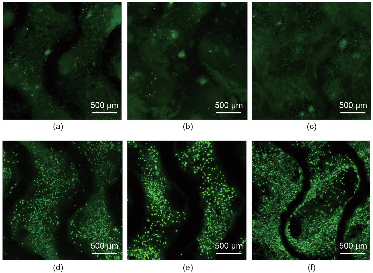
Fig. 10. Cytocompatibility of (a–c) the G scaffolds and (d–f) the G-DCPD scaffolds, where (a, d) show the results after 6 h, (b, e) show the results after 1 d, and (c, f) show the results after 3 d.
In addition, indirect cytotoxicity tests were performed to evaluate the effect of the surface treatment on cell viability and proliferation. First, Mg extracts were prepared by immersing the scaffolds in 3 mL of α-MEM under physiologic conditions (5% CO2, 37 °C) for 3 d. Then, according to the recommendation for the in vitro cytotoxicity of biodegradable Mg [42], the extracts were diluted into 15% and 30%, respectively. MC3T3-E1 cells were seeded in a 96-well plate with a density of 2000 cells per well for 24 h prior to substituting the diluted Mg extracts. After a further culturing time of 6 h, 1 d, and 3 d, respectively, 10 μL of CCK8 solution (Beyotime, China) was added to the 96-well plate and incubated for 2 h. The absorbance was recorded at 450 nm, and the relevant results are shown in Fig. 11. For the 15% extracts, all the tested samples exhibited a stimulatory effect on cell growth and no significant difference was found between the G and G-DCPD scaffolds. However, for the 30% extracts, the cell viability of the G-DCPD scaffold was higher than that of the G scaffold, and the G-DCPD scaffold exhibited an obvious stimulatory effect on osteoblast cell proliferation, indicating that the G-DCPD scaffold had good osteogenesis properties to some extent.
The rapid corrosion rate of the uncoated specimens is believed to be one of the main influencing factors behind their worse cytocompatibility in comparison with the coated scaffolds [43]. It has been reported that surface wettability has an impact on cell adhesion, and the DCPD coating has been proven to be suitable for cell proliferation [41,44]. To further validate the potential clinical applications of the AM-processed JDBM scaffolds after DCPD treatment, related in vivo studies are underway.
《Fig. 11》
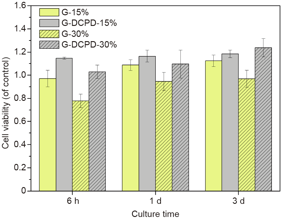
Fig. 11. Cell viability of MC3T3 cells cultured in diluted extracts of the G and G-DCPD scaffolds for 6 h, 1 d, and 3 d, respectively.
《4. Conclusions》
4. Conclusions
In this paper, we discussed the challenges and corresponding solutions for the AM of Mg-based implants. Three kinds of topologically designed Mg scaffolds with the same porosity and average pore size were additively manufactured using SLM. The AM-processed JDBM scaffolds exhibited fully interconnected structures, suitable compressive properties, and moderate corrosion behavior, thus meeting the basic requirements for tissue engineering scaffolds. Together with a cell culture assay, the present work exhibited the clinical prospects of AM-processed biodegradable Mg scaffolds with complex architectures. Furthermore, scaffolds with DCPD treatment distinctly stimulated cell proliferation due to the improvement of corrosion resistance and cytocompatibility compared with the uncoated scaffolds, indicating the necessity of surface treatment for AM-processed biodegradable Mg-based implants. The combination of biodegradation and the AM technique makes biodegradable Mg alloys attractive candidates for the next generation of orthopedic implants with complex structures.
《Acknowledgements》
Acknowledgements
This work was supported by the National Natural Science Foundation of China (51571143), the National Key Research and Development Program of China (2016YFC1102103), the Science and Technology Commission of Shanghai Municipality (19441906300, 18441908000, and 17440730700), and San-Ming Project of Medicine in Shenzhen (SZSM201612092).
《Compliance with ethics guidelines》
Compliance with ethics guidelines
Yinchuan Wang, Penghuai Fu, Nanqing Wang, Liming Peng, Bin Kang, Hui Zeng, Guangyin Yuan, and Wenjiang Ding declare that they have no conflict of interest or financial conflicts to disclose.


 京公网安备 11010502051620号


