

《1. Introduction》
1. Introduction
Modern concrete benefits from the wide use of chemical admixtures and industrial waste residues, particularly for reducing the consumption of resources and the environmental impact. The properties and durability of the materials have been improved to meet the performance requirements of modern civil engineering. However, new challenges have emerged for modern concrete. For example, early-age shrinkage is typically increased in materials with higher paste volumes [1] and lower water-to-cement ratios. Indeed, shrinkage cracking becomes severe in modern structures with long spans, large volumes and strong restraints, or under exposure to harsh environments, such as high temperature and desiccation. Engineering practices and literature have shown that shrinkage-induced cracks account for more than 80% of cracking in concrete [2]. The impermeability and resistance of concrete to the penetration of external harmful ions decrease dramatically after cracking [3]. The transmission of attack media accelerated by cracking exacerbates the degradation of material properties and the corrosion of reinforcements [4]. Thus, the service life of structures, especially for those exposed to harsh environments, can be significantly decreased. Mehta and Burrows pointed out that, to build environmentally sustainable concrete structures, the 21st century concrete practice must be driven by considerations of durability instead of strength [5]. Therefore, to improve the durability of concrete structures in engineering, cracks, especially penetrating cracks, caused by early-age shrinkage must be mitigated.
The early-age shrinkage of concrete includes plastic, autogenous, thermal, and drying shrinkages. At the plastic stage, the volumetric change of concrete manifests as a vertical settlement or a global contraction [6]. Conventionally, a theoretical model based on water evaporation and capillary pressure can be used to predict the shrinkage at this stage [7]. Some recent studies identified the bulk modulus evolution as the dominating parameter for plastic shrinkage, and a more sophisticated model has also been developed [8,9]. At the hardening stage, the shrinkage measurement of hardening concrete is mainly carried out in a standard environment with constant temperature and/or humidity. In American Society for Testing and Materials (ASTM) C1698–09 [10], measurements using corrugated tubes were designed for autogenous shrinkage starting from the casting. However, the results obtained under a standard environment cannot be directly applied to concrete structures, in which, interior humidity and temperature strongly depend on the structure sizes, external environment conditions, and concrete hydration. Shrinkage models [11] are also recommended to account for the coupling impact of different environmental factors and the interaction of different types of shrinkage.
Characterization and evaluation methods are key issues when studying early-age cracking of modern concrete. Several methods, including the slab test and ring test, can be used to characterize the key parameters of cracking for concrete materials, such as the initial cracking time, crack width, and crack area of the concrete. However, such results require further processing to be upscaled to the structural level. Zhu [12] established a theoretical system for calculating the thermal stress of concrete and proposed the threshold as a safety index for thermal cracking control of hydraulic mass concrete. Zhu also developed the ‘‘semi-mature age” concept and the long-term insulation method to mitigate cracking. Wang [2] deduced a simplified formula of thermal stress and proposed the design principle of ‘‘prevent and lay out,” as well as an alternative bay construction method for cracking control. The above theories and methods have been successfully applied to practical projects to mitigate thermal cracking in mass concrete with normal strength. Researchers from Delft University of Technology built an evaluation model for crack resistance of concrete based on maturity. They then developed two-dimensionalmodeling software that considers the effect of material varieties on structural stress [13]. However, the evolution of early-age properties, including the strength, elastic modulus, and volumetric deformation, is closely related to early-age cracking. Quantitative characterization of the influence of these properties on cracking under the conditions of variable temperature and moisture, particularly in massive concrete, remains a challenging task [14].
Shrinkage cracking can be mitigated through the quality control of raw materials and the adjustment of the concrete composition. Moderate- and low-heat cements are commonly used to reduce the temperature rise in hydraulic mass concrete. Anti-cracking materials, including expansive agents, shrinkage-reducing agents, and superabsorbent polymers, are often adopted to reduce different types of shrinkage of concrete, thereby mitigating cracking in concrete structures. Nevertheless, when used alone, commercially available anti-cracking materials have been found to be insufficient to compensate for the shrinkage in concrete construction, especially for thermal shrinkage, which leads to the incomplete prevention of cracks in modern concrete [15,16]. In addition, the lack of consideration of the temperature and humidity sensitivity of anti-crack materials also significantly limits their effect in actual structural concrete [15,17].
In this study, a formula was derived for the activation energy of the hydration reaction of a complex cementitious system containing supplementary materials, such as fly ash and slag. The hydration degree instead of time was adopted as the basic parameter to describe the evolution of concrete properties. The complex interaction between the materials and the environmental temperature and humidity was considered. Furthermore, a multi-field (hydro–thermo–hygro–constraint) coupling model, which considers the hydration and properties of the complex cementitious system of modern concrete, was introduced to calculate the shrinkage and cracking risk. The threshold of the cracking risk index was proposed based on a reliability theory.
Meanwhile, based on the mechanisms and characteristics of shrinkage of modern concrete, three key technologies—tempera ture rise inhibition, full-stage shrinkage compensation, and shrinkage reduction—were elucidated. Their use serves to effectively reduce the thermal, autogenous, and drying shrinkages of hardening concrete to reduce the cracking risk. On this basis, a simulation software and design process were developed to calculate the cracking resistance with consideration of the material compositions, structural form, environmental characteristics, and construction process of the practical structure. Finally, typical applications in subway stations and bridge towers were introduced, in which the effectiveness of the proposed methods and technologies were investigated by in situ monitoring.
《2. Shrinkage of early-age concrete》
2. Shrinkage of early-age concrete
《2.1. Activation energy of cementitious materials》
2.1. Activation energy of cementitious materials
After placement, concrete structures usually experience an obvious temperature increase, followed by a temperature decrease soon thereafter, especially for mass concrete. This temperature history depends on the heat generation of the concrete, initial casting temperature of the mixture, environment temperature, and thermal boundary conditions. Meanwhile, temperature is arguably the one variable that has the most significant effect on the rate of hydration [18]. The method based on the Arrhenius equation (Eq. (1)) is often used to characterize the effect of temperature on the development of concrete properties. The Arrhenius equation uses a parameter of activation energy to characterize the temperature sensitivity of cement hydration.

where k is the reaction rate, A is the proportionality constant, R is the natural gas constant, T is the absolute temperature, and U is the activation energy.
Recently, Maruyama and Lura [14] detailed the values of activation energy and its influencing factors. In concrete engineering, a constant value of the apparent active energy is often used. In this study, an activation energy model for cement hydration developed by Schindler [18] was adopted. Following Schindler’s model, the activation energy of cement UC can be calculated using Eq. (2), which involves the mass fractions of tricalcium silicate (C3A),  , and tetracalcium aluminoferrite (C4AF),
  , in cement, as well as cement fineness SA.

However, modern concrete is often incorporated with mineral admixtures, especially fly ash and ground granulated blast furnace slag. According to the authors’ previous studies, the hydration heat evolutions of cements were measured by an isothermal calorimeter with temperature ranging from 20 to 50 °C. Thereafter, the apparent activation energy of cementitious materials was calculated by Arrhenius plots of kinetic parameters, with its change in accordance with hydration degree ignored through averaging. Therefore, the average apparent activation energy can be calculated by Eq. (3) if the content of mineral admixtures is lower than 50% of the binder.

where Ua is the activation energy of the cementitious materials. Moreover, kFA and kSL are the influence coefficients of fly ash and ground granulated blast furnace slag, which can be determined by their mass fractions PFA and PSL, respectively, using the following equations: kFA = 1 – 0.13PFA and kSL = 1 + 0.29PSL.
《2.2. Hydro–thermo–hygro coupling effect in early-age concrete》
2.2. Hydro–thermo–hygro coupling effect in early-age concrete
After casting, the concrete material undergoes complex interactions with the environment, involving hydro–thermo–hygro coupling effects. The hydration degree of the complex cementitious materials can be adopted as the basic state parameter to calculate the concrete properties such as mechanical characteristics, hydration heat, water consumption, and transmission coefficients. In this study, the equation proposed by Cervera et al. [19] was adopted to calculate the hydration degree α:

where  , A1, and A2 are material parameters, h is the relative humidity, βh(h) is an empirical function that can be determined by fitting the experimental data (e.g., Wyrzykowski and Lura [20] and Bazˇant and Najjar [21]), and
  is the maximum hydration degree of cementitious materials that can be calculated by Eq. (5) [22]:

where w/b is the water-to-binder ratio.
Another important issue involved in this research was the determination of ‘‘time-zero,” that is, the formation time of the solid skeleton of the concrete microstructure. From then on, the shrinkage starts, it results in tensile stress under constraints. The time can be obtained by the measuring system of the meniscus depression under sealed conditions [23]. As shown in Fig. 1, ‘‘time-zero” can be determined by the peak rate of the capillary pressure (pc) of the paste. The hydration degree of the paste with different w/b corresponding to ‘‘time-zero” ( ) can be calculated by Eq. (6):

where kα is the material parameter.
Heat and moisture transfer in hydrating concrete can be described by Fourier’s law and Fick’s law, respectively (Eqs. (7a) and (7b)). The effective thermal conductivity of concrete ( ) is affected by many factors, such as the aggregate type and its volume, air content, and moisture conditions. Numerous analytical approaches for thermal conductivity have been proposed, which account for the influence of various factors, such as the hydration degree (e.g., Ruiz et al. [24]) and moisture content (e.g., Gawin et al. [25]). Meanwhile, good numerical predictions can be obtained by neglecting the change in the thermal conductivity values, especially when the heat transfer is controlled by formwork and thermal insulation materials. The total heat of the hydration reaction per unit of hydrated mass
  can be calculated from the cement components and dosage of supplementary cementitious materials [22]. The moisture permeability (Dh) is a nonlinear function of the relative humidity and temperature [21]. Before the form removal of mass concrete, the change in the internal moisture or humidity is mainly caused by hydration.


where  is the mass density of concrete, Cp denotes the specific heat of concrete, c is the cementitious material mass content, w represents the water content, and Dh is the moisture permeability.
《Fig. 1》

Fig. 1. Determination of ‘‘time-zero.”
《2.3. Shrinkage of concrete》
2.3. Shrinkage of concrete
Shrinkage of hardening concrete includes autogenous, thermal, and drying shrinkages. Autogenous and drying shrinkages mainly occur owing to the decrease in the interior humidity, which results in an increase in the meniscus depression. This phenomenon will induce an elastic and delayed strain. The delayed strain, mainly caused by creep [26], becomes more pronounced for concrete with lower w/b. It is thus not considered in this paper for concrete with w/b larger than 0.32. Thermal shrinkage occurs due to the drop in temperature caused by the heat transfer between the concrete and the environment. The total shrinkage of concrete resulting from both the decrease in interior humidity and temperature can be expressed using Eq. (8) [27–29]. In this equation, the saturation degree of concrete (Sw) can be determined by experimental methods, such as mass loss measurements of the water (e.g., Bella et al. [30]) and the sorption isotherms of the paste (e.g., Espinosa and Franke [31]). In engineering, fly ash is often used to partially replace cement in concrete, whereas slag is not added, or only a minimal amount is added, to mitigate shrinkage cracking. Given that the hydration degree of fly ash is low when cracking occurs (generally within seven days), the effect of fly ash on Sw was neglected in this study, and Sw was directly simplified as calculated by Powers’ model according to the literature [28].

where εsh is the total deformation of concrete, εh denotes the shrinkage due to humidity, εT represents the shrinkage due to temperature,  is the mass density of water, and Mw denotes the molar mass of water. Moreover, KT represents the bulk modulus of concrete, KS is the bulk modulus of the solid skeleton, βT denotes the thermal expansion coefficient of concrete, and
  is the volume of capillary water. Additionally,
  is the volume of gel water,
  is the volume of the chemical shrinkage,
  denotes the elastic modulus of concrete related to the hydration degree, and μ is Poisson’s ratio.
When appropriate boundary and initial conditions are specified, the distributions of the hydration degree, temperature, and relative humidity of the concrete structure can be calculated using Eqs. (4) and (7) in accordance with the finite element method. Thereafter, the total deformation can be calculated using Eq. (8). Fig. 2 shows the simulation and the monitored results with respect to the temperature and total deformation of a 0.7 m thick underground sidewall concrete. In the simulation, the parameters of the concrete were as follows: The seven-day adiabatic temperature rise was 55.2 °C, the 28-day autogenous shrinkage was 131.5 × 10⁻⁶ , the thermal conductivity coefficient was 8.6 kJ·m-1 ·h-1 ·K-1 , and the thermal expansion coefficient was 10 × 10-6 °C-1 . It is observed from Fig. 2 that the simulation results are in good agreement with Fig. 1. Determination of ‘‘time-zero.” the monitored results.
《Fig. 2》

Fig. 2. Simulation and monitored results on (a) temperature and (b) deformation.
《3. Cracking risk evaluation of early-age concrete》
3. Cracking risk evaluation of early-age concrete
《3.1. Early-age elastic modulus and tensile strength》
3.1. Early-age elastic modulus and tensile strength
The early-age elastic modulus and tensile strength of concrete are necessary parameters for shrinkage stress and cracking risk calculation. Here, a hydration degree-based description of the elastic modulus and tensile strength of early-age concrete in Ref. [32] was adopted:

where  is the ultimate elastic modulus of concrete,
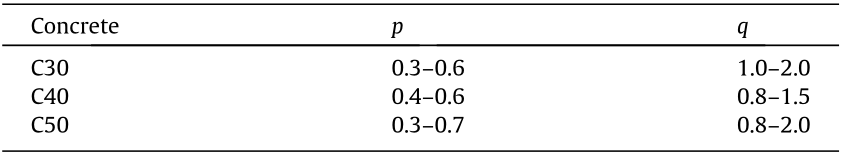
  denotes the ultimate tensile strength of concrete, and p and q are fitting parameters. Table 1 lists the fitting parameters for C30, C40, and C50 obtained by the least square regression of the experimental results tested by the temperature stress test machine and the universal testing machine. The detailed fitting process is the same as that described in the authors’ previous paper [33].
《Table 1》
Table 1 Fitting results of parameters p and q.
《3.2. Early-age creep》
3.2. Early-age creep
Creep or relaxation behavior must also be considered to calculate the stress due to shrinkage under the restriction of early-age concrete. Stress induced by restrained thermal, autogenous, and drying shrinkage can be significantly reduced by relaxation. Thus, the characterization of early-age creep or relaxation behavior is essential for the evaluation of the stress development and cracking risk of concrete. Based on the viscoelastic theory, the creep behavior of concrete can be mathematically described using different rheology models, such as the Maxwell or Kelvin chain models [26,34–36]. In this study, a Kelvin chain model was adopted to calculate the early-age creep of concrete (εc) using the following formula:

where  is the stress in the Kelvin unit,
  denotes the strain at the nth Kelvin unit,
  is the characteristic time that can be determined by trial-and-error calculation, and
  and En are the aging elastic modulus of the individual spring and springs in the Kelvin unit, respectively. The hydration degree-based evolution of En was determined using Eq. (10). In fact, the structural concrete was in the compression state owing to the temperature rise in the first few days. It then gradually changed to the tensile state, so the creep was in a compression state first and in a tension state thereafter. However, for the sake of simplification, only the compressive creep of concrete was measured using a hydraulic creep apparatus at the ages of two days, three days, seven days, 14 days, and 28 days. The creep in tension was assumed to be the same as that in compression. Then, the least squares method was used to determine En.
《3.3. Cracking risk》
3.3. Cracking risk
Based on the above formulas for the shrinkage, elastic modulus, and creep calculation, the stress of concrete induced by shrinkage under restraint could be calculated for certain structural shapes and environmental conditions by using the finite element method.
The calculation of the temperature and relative humidity field had to also satisfy the appropriate initial and boundary conditions, while satisfying the governing Eq. (6). The initial conditions, for example, the concrete placing temperature and initial instantaneous relative humidity, described the temperature and relative humidity at time t = 0. The boundary conditions described the exchange of heat and moisture between the concrete and surrounding medium at the boundary [12], such as the heat exchange between the air-exposed concrete and air, the heat transfer between the concrete surface and the insulation materials, and the heat transfer between the contact surface of the concrete and the cooling water pipe.
The restraint conditions included internal and external restrictions. The internal restriction was induced by uneven deformation, including autogenous, drying shrinkage, and thermal deformation of the different parts of the concrete itself, whereas temperature and humidity gradients may have led to shrinkage gradients. The external restrictions were mainly caused by the structural form, including the subgrade and all adjoining structures, as well as the placement sequence of the concrete. Here, the internal and external restrictions were considered based on displacement coordination.
After the initial and boundary conditions and restrictions were determined, the stress under restrictions could be calculated by the incremental finite element method:

where  is the stress increment,
  denotes the elastic matrix,
  is the total strain increment,
  represents the total shrinkage strain increment, that is, the sum of the thermal deformation increment
  and the autogenous and drying shrinkage increment
  . Moreover,
  is the creep strain increment.
In accordance with the crack criterion, the cracking risk index  is defined as

where  and
and  denote the maximum tensile stress and tensile strength of the concrete at time t, respectively. If > 1.0, the concrete will certainly crack; if ≤ 1.0, given the variability in material properties, the concrete still has the possibility of cracking.
Assuming that the tensile strength  and stress induced by shrinkage (
 ) follow a log-normal distribution [37], from the probability theory, the function
  follows a normal distribution. According to the concept of reliability, the reliability index
  can be expressed as follows:

where denotes the reliability index;  and
and  represent the mean and standard deviation of Z, respectively;
  is the coefficient of variation of tensile strength; and
  denotes the coefficient of variation of the shrinkage stress.
According to the failure probability density function, the reliability probability of 95% (i.e., the failure probability of 5%) corresponds to a reliability index of 1.64 [37,38]. According to the statistical results of the tensile strength and shrinkage stress, the variation coefficient of the tensile strength was ~0.10, and the coefficient of variation of shrinkage stress caused by thermal and autogenous shrinkages was ~0.20. According to Eq. (15), when the reliability probability reached 95%, the corresponding cracking risk index was 0.71. Thus, the threshold of the cracking risk index should have been 0.7 to ensure that the reliability probability was higher than 95%.
Fig. 3 shows the calculated cracking risk of a 0.7 m thick underground sidewall concrete by the above model and the deformation monitored by the strain gauge. The calculated results show that the cracking risk index of the concrete reaches 0.7 at approximately six days, whereas the actual monitored results show that the deformation of concrete changes abruptly in six to seven days, indicating the occurrence of concrete cracking. The calculated result is consistent with the monitored observations.
《Fig. 3》
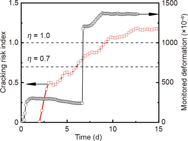
Fig. 3. Calculated cracking risk and cracking time monitored on a 0.7 m thick sidewall concrete.
《4. Key technologies for crack control》
4. Key technologies for crack control
《4.1. Concrete temperature rise inhibition technology》
4.1. Concrete temperature rise inhibition technology
The temperature rise of structural concrete depends on the total and rate of hydration heat released, as well as the heat dissipation of the structure. Generally, a lower hydration rate leads to a lower temperature rise when other conditions are the same. Fig. 4 shows the effect of cement hydration evolution on the temperature rise of structural concrete, which was simulated according to the heat transfer equation given in Eq. (6), with a specific heat capacity of 0.9 kJ·kg-1 ·K-1 . The heat dissipation coefficient is 68 kJ·m-2 ·h-1 ·K-1 , and the thermal conductivity coefficient is 8.6 kJm2 h1 K1 . This indicates that a decreased rate of heat release, particularly at the acceleration stage, effectively lowers the maximum temperature, delays the appearance of the maximum temperature, and lowers the temperature drop rate in concrete. Thus, the reduction of cement hydration heat release at the acceleration stage is a promising strategy to reduce the temperature rise of concrete.
《Fig. 4》

Fig. 4. Effect of cement hydration evolution on the temperature rise of concrete (simulation).
A concrete temperature rise inhibitor (TRI) is a novel modified starch powder that has a slow-release character and can gradually dissolve in cement pore solution. Based on our preliminary studies [39–41], TRI gradually dissolves in the pore solution and adsorbs to the surface of cement particles. Meanwhile, calcium silicate hydrate (C-S-H) nucleation is continuously inhibited, but never fully blocked. With less precipitation of C-S-H needles on the surface of cement, the hydration rate during the peak time decreases accordingly.
Fig. 5 displays the effect of TRI on the temperature rise of concrete. The concrete was cast into a 400 mm × 400 mm × 400 mm wood mold lined with 50 mm extruded polystyrene board insulation. The concrete temperature and deformation were monitored by the temperature sensors and strain gauges placed in the center of the cubes. The water-to-binder ratio was 0.42. The weight of the binder was 375 kg·m-3 , and the proportion of fly ash was 33.3% by weight of the total binder. The results show that the maximum temperature of the reference concrete (REF in short, which herein refers to concrete without anti-crack materials, the same in the following text) was ~30 °C, whereas the maximum temperature of concrete with the addition of TRI was ~18 °C. Compared with REF, the thermal shrinkage of concrete with TRI was reduced by 140 × 10–6 after ten days.
《Fig. 5》

Fig. 5. Effect of TRI on the (a) temperature rise and (b) thermal shrinkage of concrete.
《4.2. Full-stage shrinkage compensation technology》
4.2. Full-stage shrinkage compensation technology
Considering the temperature history and shrinkage process of actual structural concrete, a calcium and magnesium oxide-based expansive agent (CMA) was designed to compensate for the shrinkage of concrete at different stages [42]. The calcium oxide expansive component caused an expansion in the initial days to compensate for early-age (mainly one to three days) autogenous shrinkage. The magnesium oxide expansive component with a higher reactivity (a lower reactivity value) caused expansion during the middle period to compensate for autogenous and thermal shrinkage at the temperature drop stage. (Reactivity value is defined as the time required for neutralization with the acid solution based on the Chinese standard DL/T 5296–2013.) Additionally, the magnesium oxide expansive component with a lower reactivity (a higher reactivity value) caused a slow expansion to compensate for shrinkage in later stages.
Fig. 6 shows the test results of the autogenous deformation and drying shrinkage of C30 and C50 with and without CMA. C30 has a water-to-binder ratio of 0.45 and a binder amount of 380 kg·m-3 . C50 has a water-to-binder ratio of 0.35 and a binder amount of 460 kg·m-3 . The CMA content is 8% of the total amount of the binder. It can be observed in Fig. 6(a) that CMA reduces the autogenous shrinkage by more than 200 × 10–6. After nearly 120 days, C30 concrete still showed an expansion of more than 100 × 10–6, whereas C50 shows no significant shrinkage compared to the ‘‘time-zero” value. As depicted in Fig. 6(b), CMA reduces drying shrinkage by more than 100 × 10–6, and the drying shrinkage of C30 and C50 containing CMA is stabilized at 60 days and 28 days, respectively.
《Fig. 6》
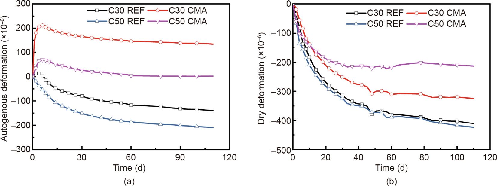
Fig. 6. Effect of CMA on autogenous and drying shrinkages of the concrete. (a) Autogenous deformation; (b) drying shrinkage.
Fig. 7 shows the monitored results of the temperature and deformation histories of C35 sidewall concrete with the thickness of 1 m. The figure reveals that the center temperature of the concrete reaches a peak value at two to three days after casting and decreases sharply thereafter. The mixture with 6% CMA causes expansion of 250 × 10–6 in the temperature rise stage and of 70 × 10–6 in the temperature drop stage. At 20 days after casting, the thermal shrinkage of concrete tends to be stable, and the concrete containing CMA remains in the expansion state to compensate for the shrinkage in a later stage.
《Fig. 7》
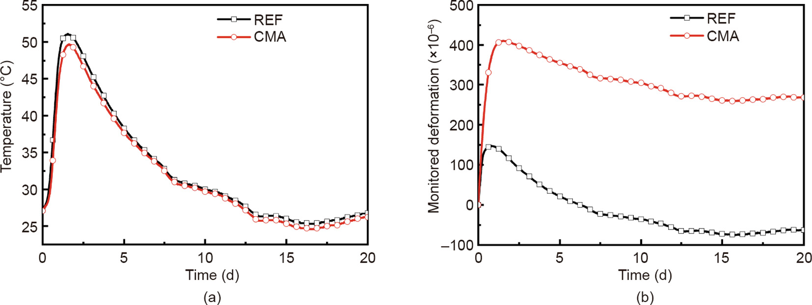
Fig. 7. Influence of CMA on deformation history of sidewall concrete. (a) Temperature history; (b) deformation history.
《4.3. Shrinkage reduction technology》
4.3. Shrinkage reduction technology
Shrinkage-reducing polycarboxylate superplasticizer (SR-PCA) is a novel concrete admixture with water- and shrinkagereducing properties. The surface tension and Na+ and K+ concentrations of the pore solution are significantly reduced by SR-PCA. This occurs because the micro-hydrophobic-modified polyether is introduced into the main chain of its molecule, thereby reducing the drying and autogenous shrinkage of the concrete. It has been confirmed in previous studies [43–45] that the reduction of Na+ and K+ in the pore solution increases the concentration of Ca2+ and the oversaturation of portlandite and ettringite, which accelerates the growth of portlandite. Moreover, the higher internal relative humidity of cement paste in the presence of SR-PCA is due to the decrease in the alkali ion concentration, the delay in cement hydration, and the decrease in surface tension [46]. Fig. 8 shows the surface tension of the synthetic pore solution consisting of 0.35 mol potassium hydroxide and 0.05 mol sodium hydroxide in 1 L deionized water according to Ref. [43]. Specifically, in a comparison of the synthetic pore solution without SR-PCA, when the mass concentration of SR-PCA was 5%, the surface tension decreased from 62.3 to 33.6 mN·m-1 . The surface tension of the simulated pore solution was reduced significantly by the addition of SR-PCA, and it gradually stabilized with the increased concentration of SR-PCA. Fig. 9 illustrates the effect of SR-PCA on the Na+ and K+ concentrations of the pore solution. After the addition of 0.4% SR-PCA, the concentrations of Na+ and K+ in the pore solution reach 926 and 11 428 mg·L-1 after 28 days and are reduced by ~52.7% and ~5.5%, respectively, compared with those in the pore solution without SR-PCA.
《Fig. 8》

Fig. 8. Effect of SR-PCA on surface tension of the simulated pore solution.
《Fig. 9》

Fig. 9. Effect of SR-PCA on Na+ and K+ concentrations of the pore solution.
Fig. 10 depicts the test results of the drying shrinkage of concrete with and without SR-PCA. It is observed that the drying shrinkage of concrete is reduced by more than 20% by the addition of 0.4% SR-PCA. The shrinkage tends to be stable at 60 days, suggesting that the use of SR-PCA can be a promising technique to reduce concrete shrinkage. Fig. 11 shows the effect of SR-PCA on the concrete cracking risk. For thin-walled concretes that are prone to shrinkage due to water loss, the estimated cracking risk can be reduced by 13.6%.
《Fig. 10》

Fig. 10. Effect of SR-PCA on drying shrinkage of concrete.
《Fig. 11》

Fig. 11. Effect of SR-PCA on concrete cracking risk.
《5. Design of the anti-cracking concrete and the typical applications》
5. Design of the anti-cracking concrete and the typical applications
《5.1. Design method for anti-cracking concrete》
5.1. Design method for anti-cracking concrete
A simulation software and design process was developed to calculate the cracking resistance of concrete structures under typical conditions, including super long structures, massive structures, prefabricated components, strongly constrained structures, high strength, and super high-strength concrete structures. As shown in the design flow in Fig. 12, after inputting the parameters, including environmental and material parameters, and the construction method, the development of hydration degree, temperature field, humidity field, and stress field are calculated. Then, the cracking risk index is obtained through the continuous adjustment of the parameters and repeated iterations until the design requirements are met.
《Fig. 12》

Fig. 12. Design flow for concrete with crack mitigation technology. TEMP & RH: temperature and relative humidity.
The design process was proposed for controlling the material parameters of the concrete (e.g., hydration heat release history, autogenous deformation, and drying shrinkage). The process can guide the rational use of functional materials (including their types, content, and technical indices) and it can be used to optimize the construction methods (e.g., molding temperature, temperature history, concrete curing method, and curing time) to control the cracking risk index below the threshold of 0.7. Fig. 13 shows the schematics of shrinkage stress regulation with crack mitigation technology (CMT).
《Fig. 13》

Fig. 13. Schematics of shrinkage stress regulation in the whole process.
《5.2. Typical engineering applications》
5.2. Typical engineering applications
5.2.1. Sidewall concrete under strong restraint
With the double restraint caused by the bottom plate and lateral envelope, cracking and leakage remain serious problems in superimposed sidewall concrete structures in subway stations. Hence, TRI and CMA were adopted to reduce the adiabatic temperature rise and autogenous shrinkage of the concrete. Fig. 14(a) shows that the reduction in adiabatic temperature rise of CMT at one day after the initial setting was ~66% compared with REF, and this effect becomes negligible at seven days. Meanwhile, the adiabatic temperature rise of anti-crack concrete at one day after the initial setting is only 25% of that at seven days. Fig. 14(b) shows that the autogenous deformation of REF at seven days and 28 days are –86 × 10–6 and –115 × 10–6, respectively, whereas the values for anti-crack concrete are 239 × 10–6 and 288 × 10–6 for anti-crack concrete, indicating that the latter remains in an expansion state.
《Fig. 14》

Fig. 14. Effect of anti-crack technology on the (a) adiabatic temperature rise and (b) autogenous deformation of concrete.
Fig. 15 shows the monitored results of the superimposed sidewall adopting CMT, inducing joint technology with an interval of inducing joint of 5 m, and ordinary concrete, respectively, in a subway station in Shanghai. The results in the figure show that the maximum cracking risk index of REF is close to 1.0, whereas it is reduced to 0.7 by utilizing CMT. The statistical results show that there are no penetrating shrinkage cracks and leakage when utilizing anti-crack concrete technology. Although the number of cracks is reduced by 20%, shrinkage cracking and leakage still occur in the superimposed sidewall with the inducing joint technology.
《Fig. 15》

Fig. 15. Long-term ambient temperature history and the corresponding cracking risk index evolution of the superimposed sidewall concrete.
5.2.2. High strength and mass concrete
The bridge tower of the Husutong Yangtze River bridge is constructed with C60-reinforced mass concrete and has a wall thickness of 1.2–4.2 m. The bridge tower concrete possesses high cracking risk under the conditions of strong internal and external restraints, and it is difficult to realize heat insulation and moisture retention. Considering both the cost and feasibility, the maximum cracking risk indices of the surface and center concrete were controlled to be under 0.7 and 1.0, respectively. The CMT concrete was prepared by incorporating TRI and CMA. Special construction measures were utilized, such as controlling the casting temperature of the concrete below 28 °C, maintaining the curing time with a template for no less than ten days, and adopting cooling pipes in the concrete structures.
Figs. 16(a) and (b) show the monitored results of temperature and deformation of the center and surface concrete. The reduction of the peak temperature of the center point and surface point of CMT is 4.7 and 3.5 °C, respectively, compared with those of REF. Meanwhile, the temperature difference between the center and surface is reduced by 3.6 °C. At the temperature rise stage, the expansion deformations of the center and surface concretes increase by 216 × 10–6 and 149 × 10–6, respectively. At the subsequent temperature drop stage, the shrinkage deformation of the center and surface concretes is reduced by 82 × 10–6 and 60 × 10–6, respectively. The maximum cracking risk index is reduced from 1.20 to 0.73 for the center concrete and from 0.92 to 0.64 for the surface concrete (Fig. 16(c)). After one year of observation, it was found that the average number of cracks in the bridge tower was reduced by ~80% when utilizing CMT, and no visible cracks were observed in segments where all the actual construction measures successfully met the design requirements.
《Fig. 16》

Fig. 16. Monitoring results and cracking risk index of bridge tower concrete. (a) Temperature; (b) deformation; (c) cracking risk index.
《6. Conclusions》
6. Conclusions
The aim of this study was to develop a theoretical model and strategies that can be used to evaluate the cracking risk and mitigate the shrinkage cracking of hardening concrete in engineering with consideration of the extensive influence of concrete materials on structures.
In the theoretical model, considering the complex cementitious system of modern concrete, a formula for the activation energy of the overall hydration reaction of the cementitious system containing supplementary cementitious materials was derived. In addition, the hydration and corresponding mechanical properties with a multi-field (hydro–thermo–hygro–constraint) coupling model was combined with the abovementioned formula to calculate the cracking risk index of structural concrete. The effects of anti-cracking materials on hydration and shrinkage can also be considered in the model.
Three novel anti-cracking materials were illustrated: concrete temperature rise inhibitor, calcium and magnesium oxide-based expansive agent, and shrinkage-reducing polycarboxylate superplasticizer. Their efficacy on the reduction of temperature rise, shrinkage, and cracking risk were monitored in concrete elements or simulated by the theoretical model.
A design method was proposed based on the theoretical model and technologies to control the cracking risk index of structural concrete below the threshold. Engineering application results showed that concrete shrinkage cracking can be significantly mitigated by adopting the proposed method and technologies.
《Acknowledgements》
Acknowledgements
This research was financially supported by the National Key R&D Program of China (2017YFB0310100), the National Basic Research Program of China (2015CB655105), and the National Outstanding Youth Science Foundation Program (51225801).
《Compliance with ethics guidelines》
Compliance with ethics guidelines
Jiaping Liu, Qian Tian, Yujiang Wang, Hua Li, and Wen Xu declare that they have no conflict of interest or financial conflicts to disclose.


 京公网安备 11010502051620号


