

《1. Introduction》
1. Introduction
It is well-known that the interfacial transition zone (ITZ) between aggregate and cement paste differs distinctly from that of cement paste in terms of their microstructures and compositions [1,2]. This ITZ, which is typically 20–50 μm thick, is characterized by higher porosity, lower modulus and hardness, and lower strength than cement paste [3]. The ITZ forms mainly as a result of the wall effect, flocculation effect, and one-side growth effect [4]. This zone acts as the weakest phase in concrete at the mesoscale, thus determining the performance of concrete to a certain extent [5,6]. Therefore, numerous techniques have been applied to improve the properties of the ITZ between aggregate and cement paste, such as using pretreated aggregate [7–9] or mineral admixtures [10–12].
In addition, incorporating nanofillers can also improve the performance of the ITZ. Zhang et al. [13,14] suggested that the presence of nanosilica can refine the pores in the ITZ and prevent the ITZ from being the weakest phase in concrete at the mesoscale. Wang et al. [15] studied the effects of eight types of nanofillers (including nanoparticles, nanotubes, and nanosheets) on the ITZ between aggregate and cement paste. Experimental results demonstrated that all types of nanofillers can notably improve the bond strength of the ITZ. This modification of nanofillers can be achieved by an approach called ‘‘bottom up,” in which concrete is modified at the nanoscale, which in turn affects structures and properties from the micro- to the macroscale [16–22]. Owing to the unique nano-core effect, the nanofillers together with absorbed calcium silicate hydrate (C–S–H) gels form nano-core–shell elements at the nanoscale. Researchers hypothesized that this is the underlying mechanism of nanofillers on the mechanical properties of concrete [23,24]. However, direct experimental evidence on the characteristics of these nano-core–shell elements is lacking owing to their small size.
With the development of nanoindentation techniques, new opportunities are now available to characterize the intrinsic nanomechanical properties of phases in concrete at the nanoscale [25,26]. In addition, a quantitative analytical method called the statistical nanoindentation technique (SNT) has been employed to identify the nanomechanical properties and volume fraction of each phase via a probability distribution function [27,28] or maximum likelihood estimation [29,30]. Using these techniques, many studies have examined the effects of nanofillers on concrete at the nanoscale. These studies suggested that the presence of nanofillers can improve the nanomechanical properties of C–S–H gels [31-36]. However, few studies have explored the effects of nanofillers on the ITZ between aggregates and cement paste at the nanoscale. The working mechanism of nanofillers in the ITZ may differ from that in concrete because of the unique characteristics of the ITZ. With respect to the critical role of the ITZ in influencing the properties of concrete, a study on the nanomechanical characteristics of the ITZ will enable a deeper understanding of the effects and mechanism of nanofillers on concrete from the bottom to the top.
Thus, the aim of this study is to investigate the effects of nanofillers on the ITZ between aggregate and cement paste. First, the nanoindentation technique is applied to characterize the distribution of phases of cement paste in the ITZ. Then, the content and properties of each phase in the ITZ are quantitatively analyzed using the SNT. Finally, micromechanical modeling is conducted to reveal the working mechanism of nanofillers in the ITZ.
《2. Materials and experiments》
2. Materials and experiments
《2.1. Specimen preparation》
2.1. Specimen preparation
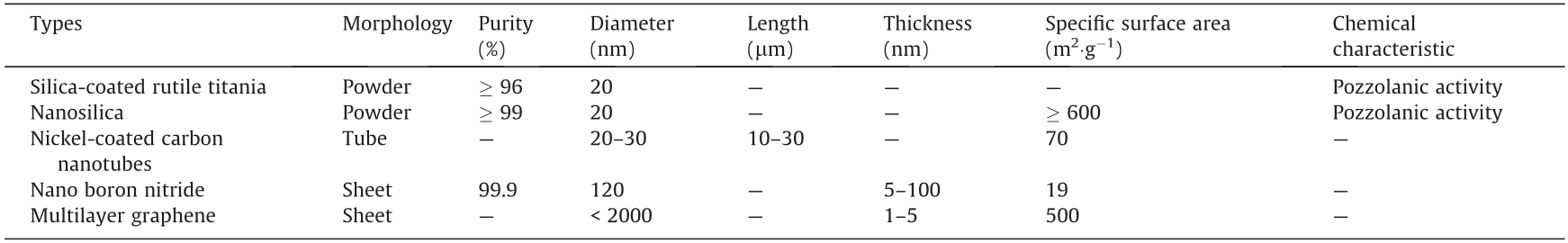
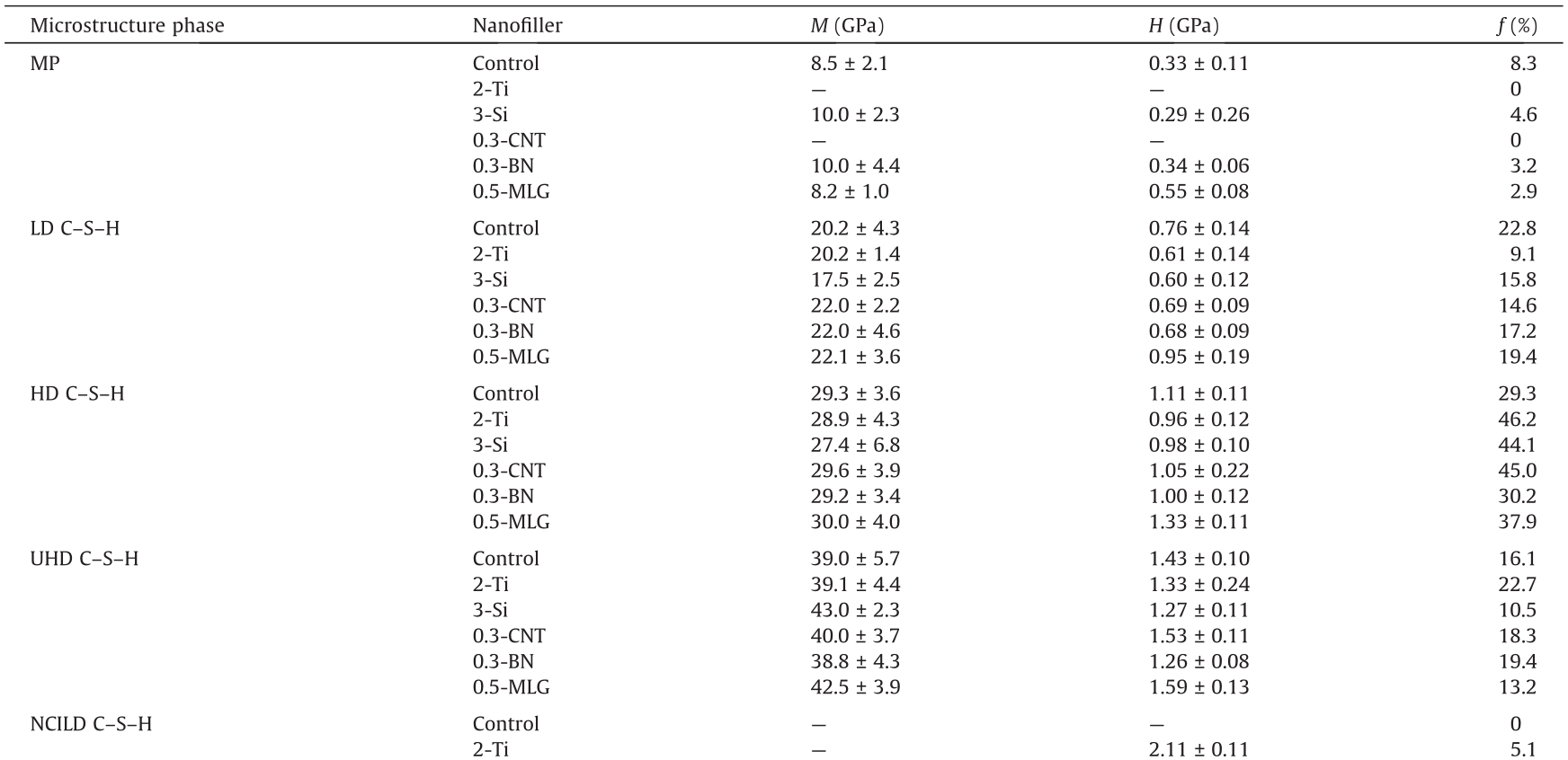
The raw materials used in this study included Portland cement with a grade of 42.5 R, class-II fly ash, silica fume with particle sizes of 0.05–0.15 μm, water, a superplasticizer with 30% reducing water capability, limestone, and nanofillers. Five representative types of nanofillers (including 0D, 1D, and 2D) were used; their physical properties are listed in Table 1. The dosages of different types of nanofillers were determined on the basis of the highest ITZ strength achieved according to the literature [15].
《Table 1》
Table 1 Physical properties of nanofillers.
Specimen preparation included two main parts: specimen fabrication and pretreatment. The specimen fabrication process included four steps: ① The limestone was cut into cubes of 40 mm × 40 mm × 80 mm and placed on one side of the oiled molds of 40 mm × 40 mm × 160 mm, ② raw materials were weighed according to the mix proportions (Table 2) and then mixed into fresh cement paste, and ③ the fresh cement paste was poured into the other side of the molds. The specimens were then demolded after curing at a temperature of 20 °C and 95% relative humidity for 24 h. ④ The specimens were cured in water at (20 ± 1) °C for 28 d and then in air for ~180 d. The detailed procedure for specimen fabrication can be found in Ref. [15]. The specimen pretreatment process involved five steps to ensure the validity of the nanoindentation results [37,38]. These included ① cutting, where sliced specimens with a sheet diameter of ~10 mm were cut in the area that included the ITZ; ② mounting, where the cut specimens were dried at 60 °C for 24 h and then mounted in cylindrical phenolic resin; and ③ grinding and polishing, where the surfaces of the specimens were successively ground using a series of sandpapers (P100, P400, P800, P1500, and P3000). The specimens were then polished using a velvet polishing cloth with 0.5 and 0.04 μm polishing agents in turn. Ethanol was used as the cooling and washing medium throughout the entire process to retain the original hydration products. ④ Cleaning, where the specimens were cleaned using ethanol in an ultrasonic vibrator to remove fragments and impurities, and ⑤ drying, where the specimens were dried at 60 °C for 24 h before being subjected to nanoindentation.
《Table 2》
Table 2 Mix proportions.
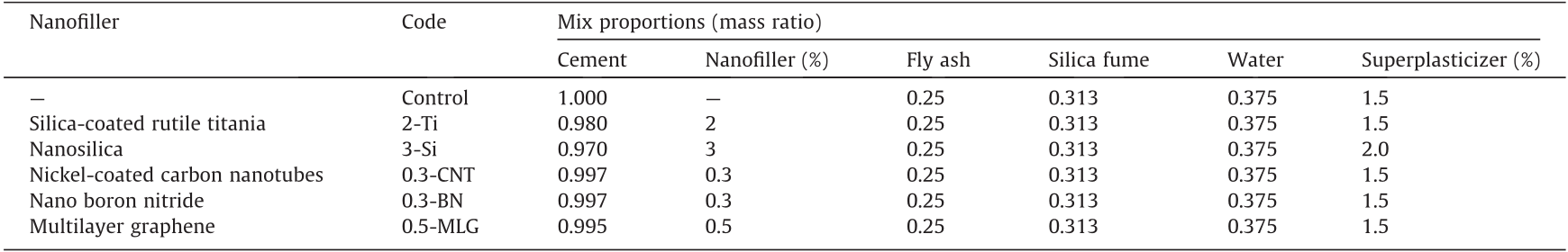
CNT: carbon nanotubes; BN: boron nitride; MLG: multi–layer graphene.
《2.2. Experimental methods》
2.2. Experimental methods
To characterize the nanomechanical characteristics of the ITZ, the nanoindentation technique and SNT were applied to each specimen. In the nanoindentation tests, the high heterogeneity and time-dependent characteristics (such as creep) of concrete at the microscale can significantly affect the experimental results. Therefore, to ensure the validity of the nanoindentation results, carefully selecting the appropriate parameters for the nanoindentation test is necessary. These include the maximum penetration depth (hmax), loading–unloading program, and grid spacing.
To identify the nanomechanical characteristics of phases in the ITZ, the maximum penetration depth needed to strictly satisfy the scale separability condition and 1/10 rule of thumb [39] is expressed as

where d represents the characteristic size of the maximum inhomogeneity of the composites, and D is the characteristic size of the microstructure. For concrete, the typical values of d and D are approximately 5 nm and 1–3 μm, respectively [39]. Therefore, the peak load of the Berkovich indenter was selected in this study to be 2 mN, and the corresponding hmax value ranged from 100 to 400 nm.
In addition, a loading–holding–unloading process was applied to eliminate the size effect caused by short-term creep. The corresponding times of loading, holding, and unloading were 15, 30, and 15 s, respectively. The load–depth curves of the different nanoindentation tests are illustrated in Fig. 1. The figure shows that the h of different nanoscale phases in the ITZ ranged from 100 to 400 nm and the shapes of the load–depth curves were normal according to previous studies [37,40]. Therefore, the results of the nanoindentation test in this study were valid, and the indentation modulus M and hardness H could be calculated using the functions proposed by Oliver and Pharr [41].
《Fig. 1》

Fig. 1. Typical load–depth curves of different phases of cement paste in concrete.
For quantitative analysis of the nanoscale phases in the ITZ, SNT was applied on the basis of a grid indentation test. The SNT regarded each nanoindentation test as an independent statistical event and then performed quantitative statistical analysis on all the results. In general, to ensure that each indentation test is conducted independently, the grid spacing should be greater than 3 μm [42,43]. In addition, the thickness of the ITZ in concrete with nanofillers should be ~20 μm according to Ref. [15]. Therefore, a 7 × 11 grids nanoindentation test with a grid spacing of 5 μm (as shown in Fig. 2) was performed on randomly selected regions, including the ITZ, of each specimen in this study.
《Fig. 2》
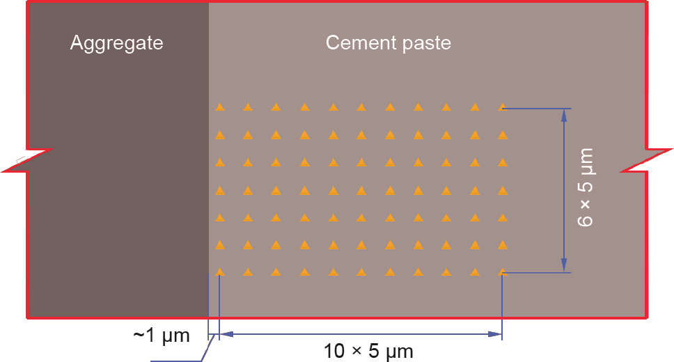
Fig. 2. Schematic of grid nanoindentation test (yellow triangle represents one location in nanoindentation test).
The grid nanoindentation data can be analyzed by deconvoluting the values of the indentation modulus and hardness using a theoretical probability density function (PDF) [44], given as

where μJ and sJ represent the mean and standard deviation of phase J (J = 1, 2, ..., n), respectively; fJ is the volume fraction of phase J (J = 1, 2, ..., n); Pi is the value of the frequency density of the experimental data; and P (xi) is the value of the theoretical probability distribution function at xi. In this study, the distribution of phase J (J = 1, 2, ..., n) in the ITZ was assumed to follow a Gaussian distribution, as shown in Eq. (3). To ensure the repeatability of the SNT analytical result, the mean μJ and standard deviation sJ of adjacent Gaussian peaks were restricted using Eq. (4). In addition, minimization was conducted for the frequency distribution of the indentation modulus M and the hardness H simultaneously. Moreover, the number of bins m must be greater than the number of unknowns in the deconvolution process 5n – 1. The deconvolution results can be used to derive the volume fraction of each phase in the ITZ as well as the mean and standard deviation of the indentation modulus and hardness.

《3. Results and discussion》
3. Results and discussion
《3.1. Nanoindentation results》
3.1. Nanoindentation results
Nanoindentation tests were conducted in this study to characterize the phase distribution in the ITZ. Figs. 3 and 4 show the contour maps of the indentation modulus and hardness based on the grid nanoindentation test, in which the blue area (i.e., the lower modulus and hardness area) near the surface of the aggregate indicates the existence of the ITZ. Fig. 5 shows the distribution of the indentation modulus and hardness extending perpendicular to the aggregate surface. As these figures show, a region with low indentation modulus and hardness existed near the interface, which is consistent with the characteristics of the ITZ, as described in Ref. [38]. As the distance between the test point and interface increased, the modulus and hardness gradually increased and tended to stabilize. The indentation modulus and hardness stabilized at a distance of 30–50 μm from the interface. This indicates that the selected test region contained a complete ITZ and a portion of the bulk cement paste.
《Fig. 3》
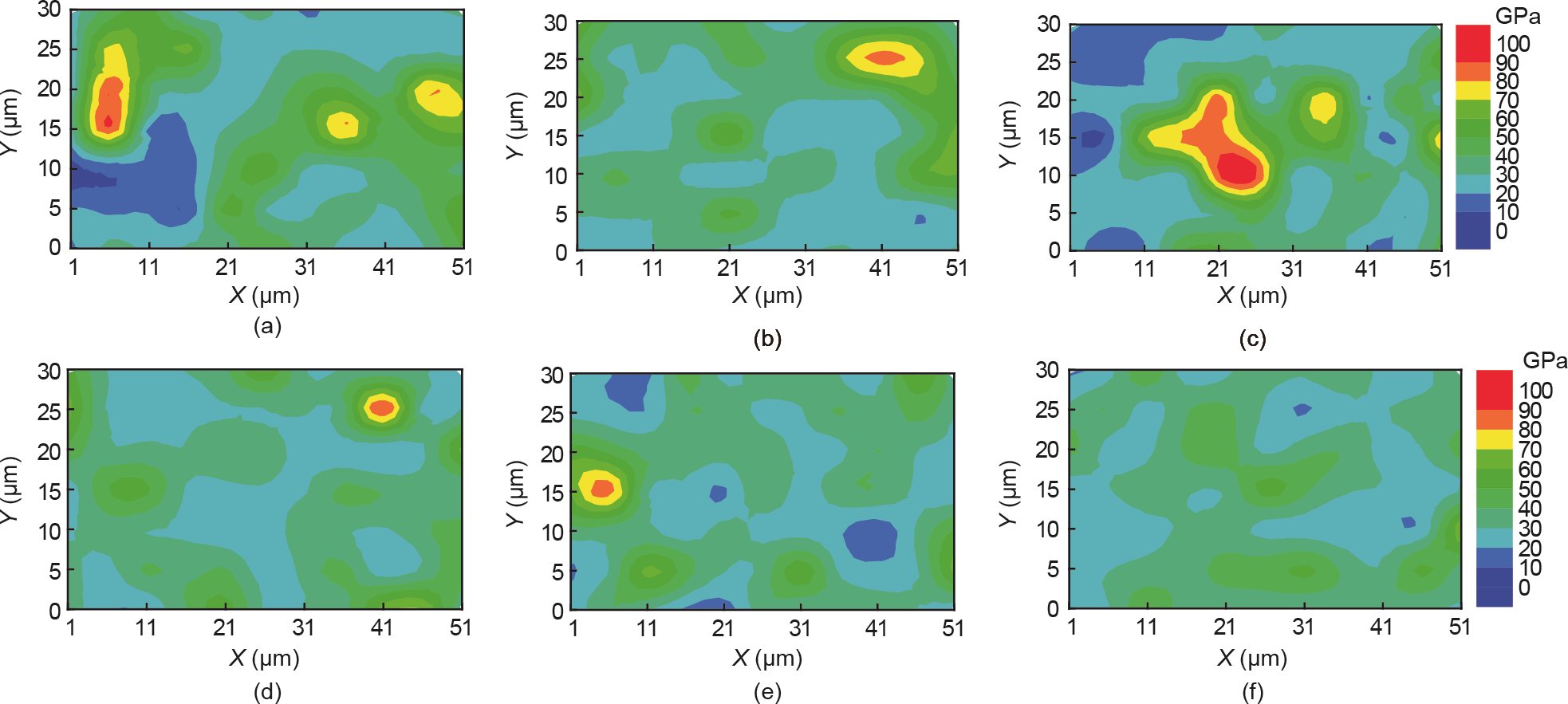
Fig. 3. Contour map of indentation modulus in ITZ between aggregate and cement paste. (a) Control group; (b) 2-Ti; (c) 3-Si; (d) 0.3-CNT; (e) 0.3-BN; (f) 0.5-MLG.
《Fig. 4》
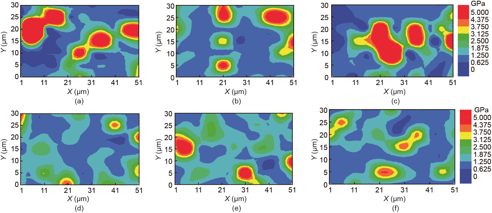
Fig. 4. Contour map of hardness in ITZ between aggregate and cement paste. (a) Control group; (b) 2-Ti; (c) 3-Si; (d) 0.3-CNT; (e) 0.3-BN; (f) 0.5-MLG.
Figs. 3–5 reveal that the indentation modulus and hardness of the ITZ in concrete without nanofillers were 0.70 and 0.59 times those of the bulk cement paste, respectively. After various nanofillers were incorporated, the indentation modulus of the ITZ in concrete ranged from 0.83 to 0.98 times that of bulk cement paste, and the hardness of the ITZ in concrete with nanofillers ranged from 0.68 to 1.41 times that of bulk cement paste. Therefore, our results revealed that all types of nanofillers can improve the nanomechanical properties of the ITZ. It should be noted that the effects of nanofillers on the nanoindentation modulus and hardness of the ITZ were different. The indentation modulus of the ITZ could only approximate but not exceed that of the cement paste in all groups. However, the ITZ hardness levels of groups 2-Ti, 0.3-Ni, and 0.5-MLG were even higher than those of cement paste. These differences could be attributed to the effects of nanofillers on the ITZ between aggregate and cement paste, which is discussed in greater detail in Section 3.2.
《Fig. 5》
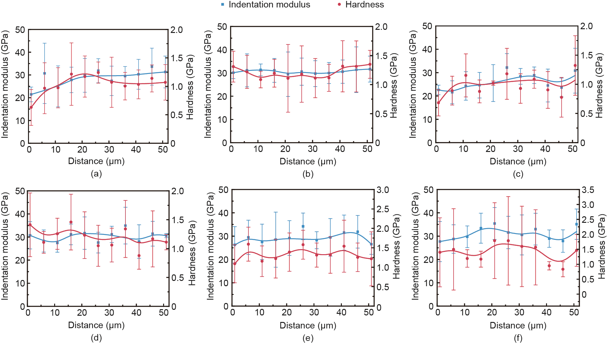
Fig. 5. Indentation modulus/hardness distributions across ITZ between aggregate and cement paste. (a) Control group; (b) 2-Ti; (c) 3-Si; (d) 0.3-CNT; (e) 0.3-BN; (f) 0.5-MLG.
《3.2. SNT analytical results》
3.2. SNT analytical results
The nanomechanical properties and volume fractions of the phases in the ITZ between the aggregate and cement paste were analyzed by applying SNT. Figs. 6 and 7 and Table 3 show the PDF deconvolution results for the indentation modulus and hardness, and Fig. 8 shows the volume fraction distribution of phases in the ITZ.
《Fig. 6》
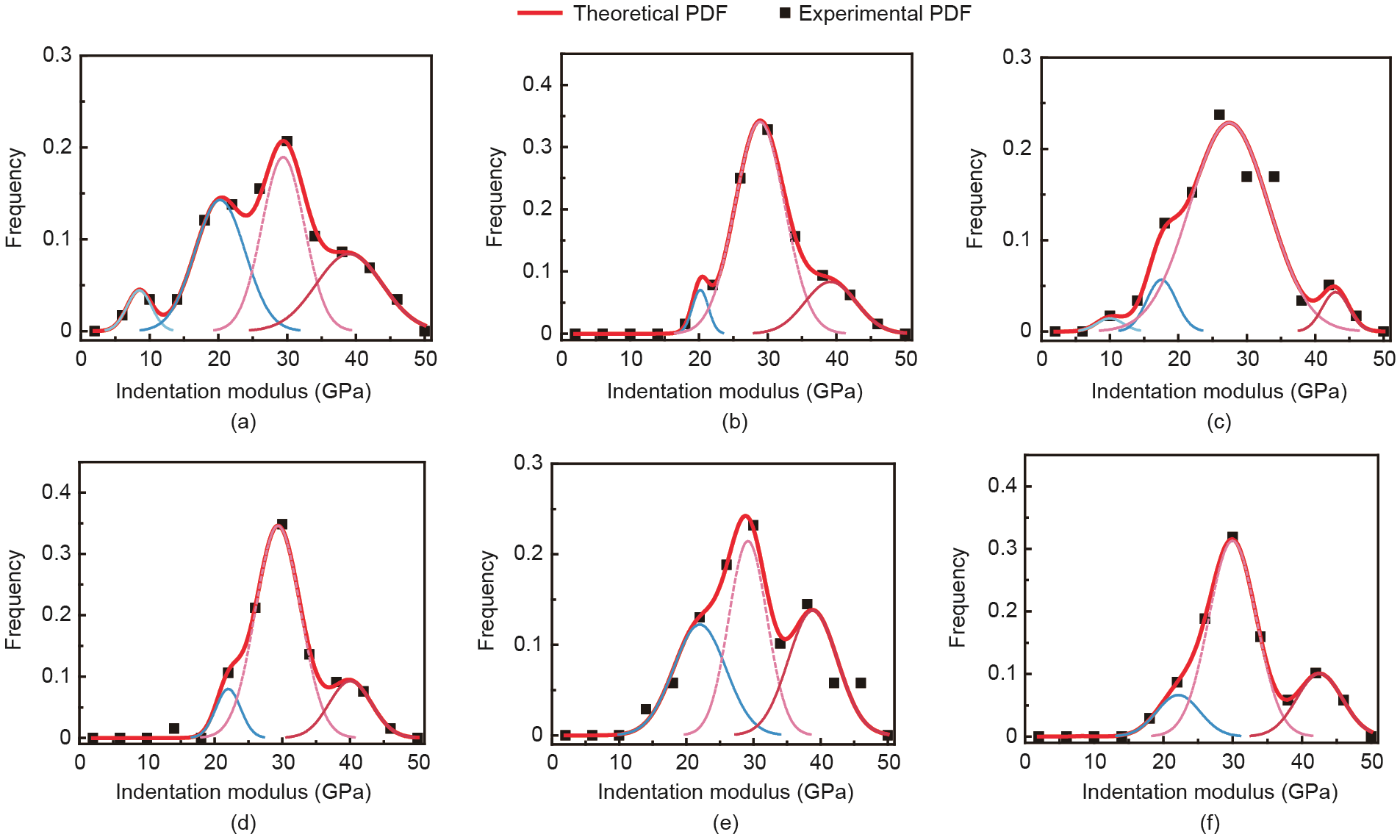
Fig. 6. Experimental frequency plots and theoretical deconvolution results of indentation modulus of grid nanoindentation tests in ITZ. (a) Control group; (b) 2-Ti; (c) 3-Si; (d) 0.3-CNT; (e) 0.3-BN; (f) 0.5-MLG.
《Fig. 7》

Fig. 7. Experimental frequency plots and theoretical deconvolution results of the hardness of grid nanoindentation tests in the ITZ. (a) Control group; (b) 2-Ti; (c) 3-Si; (d) 0.3- CNT; (e) 0.3-BN; (f) 0.5-MLG.
In this study, because of the complex composition of the binder (including cement, fly ash, and silica fume), unhydrated binder (UB) was excluded from the deconvolution analysis. The phase with an indentation modulus greater than 50 GPa was considered as the UB in the ITZ [37]. Table 3 and Fig. 8 show that the addition of nanofillers reduced the content of UB in the ITZ, indicating that the hydration degree was promoted by nanofillers. The results of the PDF analysis showed that four phases could be observed in the ITZ between the aggregate and cement paste without nanofillers. In addition, a new phase was identified in the ITZ as a result of the incorporation of nanofillers. Based on the indentation modulus from low to high, the following phases were identified:
《Table 3》
Table 3 Deconvolution results of indentation modulus M and hardness H.

《Fig. 8》
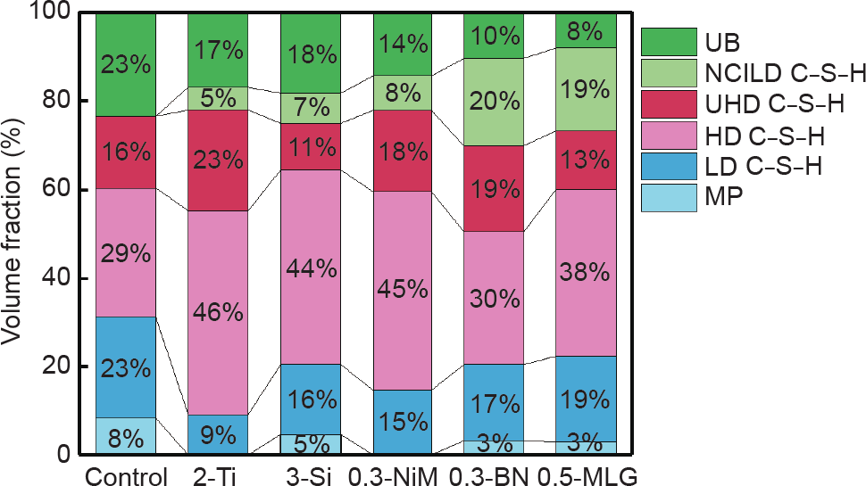
Fig. 8. Volume fraction distribution of each phase in the ITZ.
(1) Micropore (MP) with an indentation modulus M1 = μM1 ± sM1 = (9.1 ± 2.4) GPa and hardness H1 = μH1 ± sH1 = (0.38 ± 0.13) GPa accounted for 8.3 vol% in the ITZ of the control group, where μ and s represent the mean and standard deviation, respectively. The content of the MP decreased to less than 5 vol% when nanofillers were added. In particular, no MPs were observed in the 2-Ti and 0.3-CNT groups. Note that the indentation modulus and hardness of the MP were both 0 GPa. In the deconvolution analysis, the indentation modulus and hardness of the MP were similar to those of solid phases containing MPs in the ITZ. The nanomechanical properties of the MP were analyzed in this study because of their reference value for multiscale numerical simulation [39].
(2) Low-density C–S–H (LD C–S–H) with an indentation modulus M2 = μM2 ± sM2 = (20.8 ± 3.1) GPa and hardness H2 = μH2 ± sH2 =(0.72 ± 0.13) GPa occupied a volume fraction of 22.8% in the ITZ of the control group. The contents of LD C–S–H in the ITZ of the 2-Ti, 3-Si, 0.3-CNT, 0.3-BN, and 0.5-MLG were reduced to 9.1, 15.8, 14.6, 17.2, and 19.4 vol%, respectively.
(3) High-density C–S–H (HD C–S–H) with an indentation modulus M3 = μM3 ± sM3 = (29.1 ± 4.3) GPa and hardness H3 = μH3 ± sH3 = (1.07 ± 0:13) GPa occupied a volume fraction of 29.3% in the ITZ of the control group. After incorporation of nanofillers, the contents of HD C–S–H in the ITZ of the 2-Ti, 3-Si, 0.3-CNT, 0.3-BN, and 0.5-MLG increased to 46.2, 44.1, 45.0, 30.2, and 37.9 vol%, respectively.
(4) Ultrahigh-density C–S–H (UHD C–S–H) is a phase that was first discovered by Vandamme et al. [44]. The nanomechanical properties of this phase are similar to those of calcium hydroxide (CH). Therefore, the UND C–S–H and CH cannot be distinguished by nanoindentation techniques [44]. In our experiment, the water–binder ratio was low (0.24), and large amounts of SF and FA with pozzolanic activity were incorporated into the concrete. Under this condition, it could be deduced that the CH content was low in the specimens [10,45]; therefore, CH was ignored in this study. The indentation modulus of UHD C–S–H was M4 = μM4 ± sM4 = (40.4 ± 4.1) GPa and the hardness was H3 = μH3 ± sH3 = (1.40 ± 0.13) GPa based on the deconvolution results. The contents of UHD C–S–H in the ITZ of the control group, 2-Ti, 3-Si, 0.3-CNT, 0.3-BN, and 0.5-MLG were 16.1, 22.7, 10.5, 18.3, 19.4, and 13.2 vol%, respectively.
(5) Nano-core-induced low-density C–S–H (NCILD C–S–H) is a new phase that was identified in this experiment. According to Ref. [37], the nanomechanical properties for a given phase in cement paste are very stable despite different water-to-cement ratios and curing conditions as well as the age of the test. This indicates that the nanomechanical properties are the intrinsic performances of the phases in cement paste. The nanomechanical properties of the phases of cement paste in our experiment were consistent with this conclusion. In this study, a new phase characterized by a superior hardness of (2.50 ± 0.23) GPa and an indentation modulus similar to that of HD C–S–H or UHD C–S–H was identified. The new phase occupied a volume fraction of 5.1%– 19.7% in the ITZ of concrete with nanofillers, indicating that the new phase was the main component of cement paste.
According to Ref. [37], the indentation modulus and hardness of the new phase are distinctly different from all the main phases identified in cement paste, such as hydration products (LD C–S–H, HD C–S–H, UHD C–S–H, and CH) and UBs (cement, fly ash, and silica fume). In addition, the new phase was identified only in the specimens with (and not those without) nanofillers. Therefore, the new phase (NCILD C–S–H) was identified as neither the aforementioned hydration product nor the UB but instead a new hydration product altogether derived from the incorporation of nanofillers. The unique nanomechanical properties of NCILD C–S–H may be attributed to the presence of nano-core–shell elements in LD C–S–H, which is discussed in greater detail later in this section.
The nanoindentation and SNT analytical results revealed that owing to the addition of nanofillers, the degree of hydration in the interface area increased. In addition, the contents of MP and LD C–S–H in the ITZ decreased, whereas those of HD C–S–H and UHD C–S–H increased. These phenomena could be attributed to both the ITZ characteristics and nano-core effect of the nanofillers.
During the formation of the ITZ in concrete, small particles in the fresh concrete are transferred to the aggregate surface, whereas large particles move away from the surface. This is known as the wall effect [5]. In addition, the pores near the surfaces of the inactive aggregates could be filled only by the hydration products of the binders. This is known as the one-side growth effect [6]. In addition, the solubilities of the components and migration speeds of ions varied greatly during the hydration process. The siliceous composition migrated slowly and tended to deposit near the surface of the binder particles. By contrast, irons such as Ca3+ and Al3+ tend to enter the solution and migrate to the surface of the aggregate because of their fast migration, resulting in the formation of CH and ettringite near the surfaces of aggregates [6]. In the case of the ITZ in concrete modified with nanofillers, the hydration process of the ITZ was improved by nanofillers exhibiting unique nano-core effects, as shown in Fig. 9.
《Fig. 9》
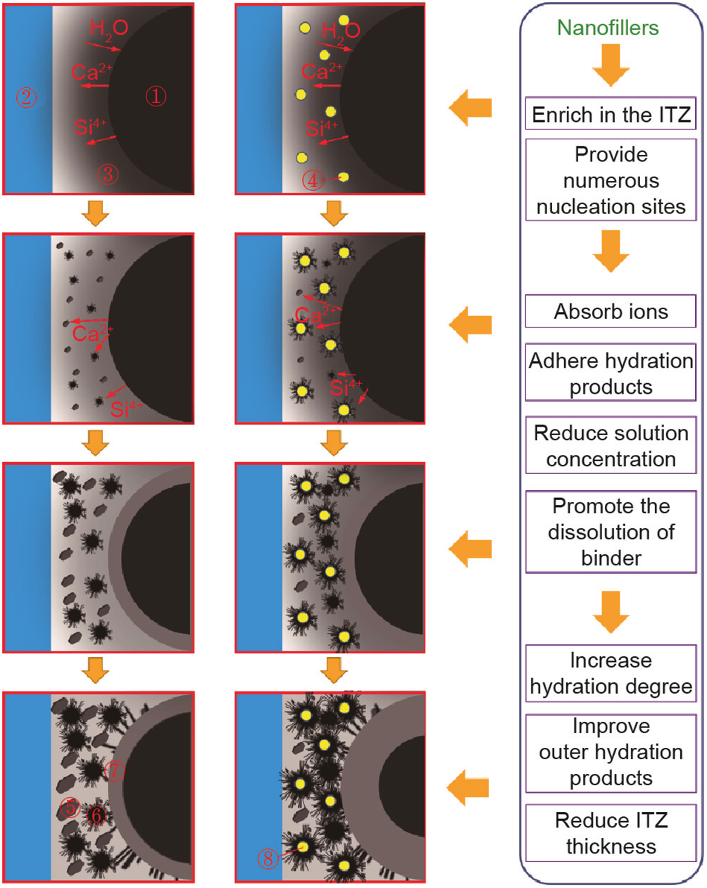
Fig. 9. Effects of nanofillers on the hydration process in ITZ. ① Binder particle (including cement, fly ash, and silica fume); ② aggregate; ③ solution the higher the concentration, the darker the color); ④ nanofiller; ⑤ CH crystal; ⑥ outer hydration products; ⑦ inner hydration products; ⑧ hydration products with nano-core.
In fresh cement paste, numerous nanofillers are enriched between aggregates and binder particles owing to the wall effect and nanofiller migration effect [15], which results in numerous nucleation sites being generated in the ITZ. Then, the ions in the solution are absorbed by the nanofillers at the initial stage of hydration owing to the high surface energy of nanofillers [23,24]. The absorption of ions leads to hydratable substance precipitation, hydration, and growth on the surfaces of nanofillers and finally forms numerous nano-core–shell elements. These effects reduce the concentration of the fresh cement solution, promote the further dissolution of binder particles, and increase the volume of the binder particles participating in the hydration, thus increasing the degree of hydration.
In addition, considering that the initial porosities of the fresh cement paste in this study were similar (where the ratio of water-to-binder was fixed), a higher degree of hydration means that a greater number of hydration products fill the pores among the aggregate and binder particles, thereby reducing the porosity of the ITZ. Moreover, the formation of nano-core–shell elements is also beneficial for improving the outer hydration products (mostly LD C–S–H [10,45-49]). Therefore, the presence of nanofillers densifies the microstructures of LD C–S–H, making its properties similar to those of HD C–S–H or UHD C–S–H.
This explains the fact that the contents of MP and LD C–S–H were reduced in the ITZ between the aggregate and concrete modified with nanofillers compared with that without nanofillers, and the contents of other C–S–H exhibiting a higher performance (namely HD C–S–H, UHD C–S–H, and NCILD C–S–H). Therefore, the addition of nanofillers densifies the microstructures of the ITZ, making the performance of ITZ approximate that of bulk cement paste.
《3.3. Micromechanical modeling》
3.3. Micromechanical modeling
In this study, a new phase named NCILD C–S–H was observed. The new phase was characterized by an indentation modulus similar to that of HD C–S–H or UHD C–S–H, but with a hardness significantly greater than that of any type of C–S–H gel. Because the C–S–H gel itself can be regarded as a porous material, the indentation modulus and hardness of each indentation can be regarded as the combined responses of the solid and pore phases.
The indentation modulus M and hardness H can be calculated using Eqs. (5) and (6) [44], respectively:

where ms and hs are the indentation modulus and hardness value of the C–S–H gel, respectively, assuming a bulk density η = 1. Note that ms is related to the solid’s Young’s modulus Es and Poisson’s ratio vs, whereas hs is related to the cohesion cs and friction coefficient αs [44].

Where A = 4.76439, B = 2.5934, C = 2.1860, and D = 1.6777 [49]. In addition, ηi is the packing density of the C–S–H gel. When the value of ηi is greater than 0.6, the influence of particle size on the nanomechanical properties can be negligible [49]. In addition, η0 is the percolation threshold of the solid (i.e., the minimum packing density of the solid that can withstand an external force). According to a previous study, η0 is equal to 0.5 [39]. Note that this study assumed a Poisson’s ratio of vs = 0.2 as the sensitivity to the Poisson’s ratio of the solid is very less [44]. Based on linear micromechanics, the indentation modulus can be related to the bulk density as follows:

Similarly, based on nonlinear micromechanics, the hardness can be related to the bulk density as
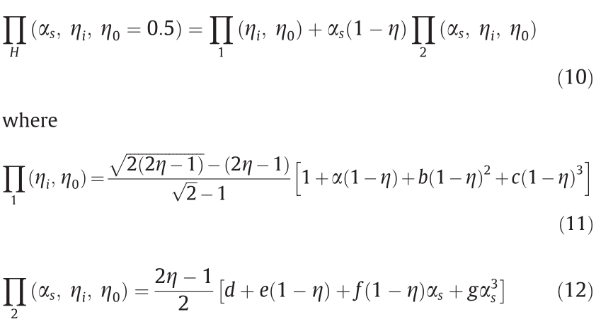
where  = –5.3678, b = 12.1933, c = –10.3071, d = 6.7374, e = –39.5893, f = 34.3216, and g = –21.2053 are all constants when the Berkovich indenter is used in the process of nanoindentation [39]. In addition, in this study, the value of ms = – 61.5 GPa was set according to the molecular dynamics results derived from Ref. [50]. The analytical results of the package density are shown in Fig. 10.
As Fig. 10 shows, the packing densities of different types of C–S–H can be obtained. The bulk densities of LD C–S–H, HD C–S–H, and UHD C–S–H were 68.2% ± 2.5%, 74.5% ± 2.7%, and 81.3% ± 2.5%, respectively. For NCILD C–S–H, this model was only partially applicable when the fitting parameters were unchanged. On the one hand, the indentation modulus of NCILD C–S–H was equivalent to that of HD C–S–H and UHD C–S–H, and its modulus could be well expressed by the aforementioned model, indicating that NCILD C–S–H densified the packing density of LD C–S–H.
《Fig. 10》
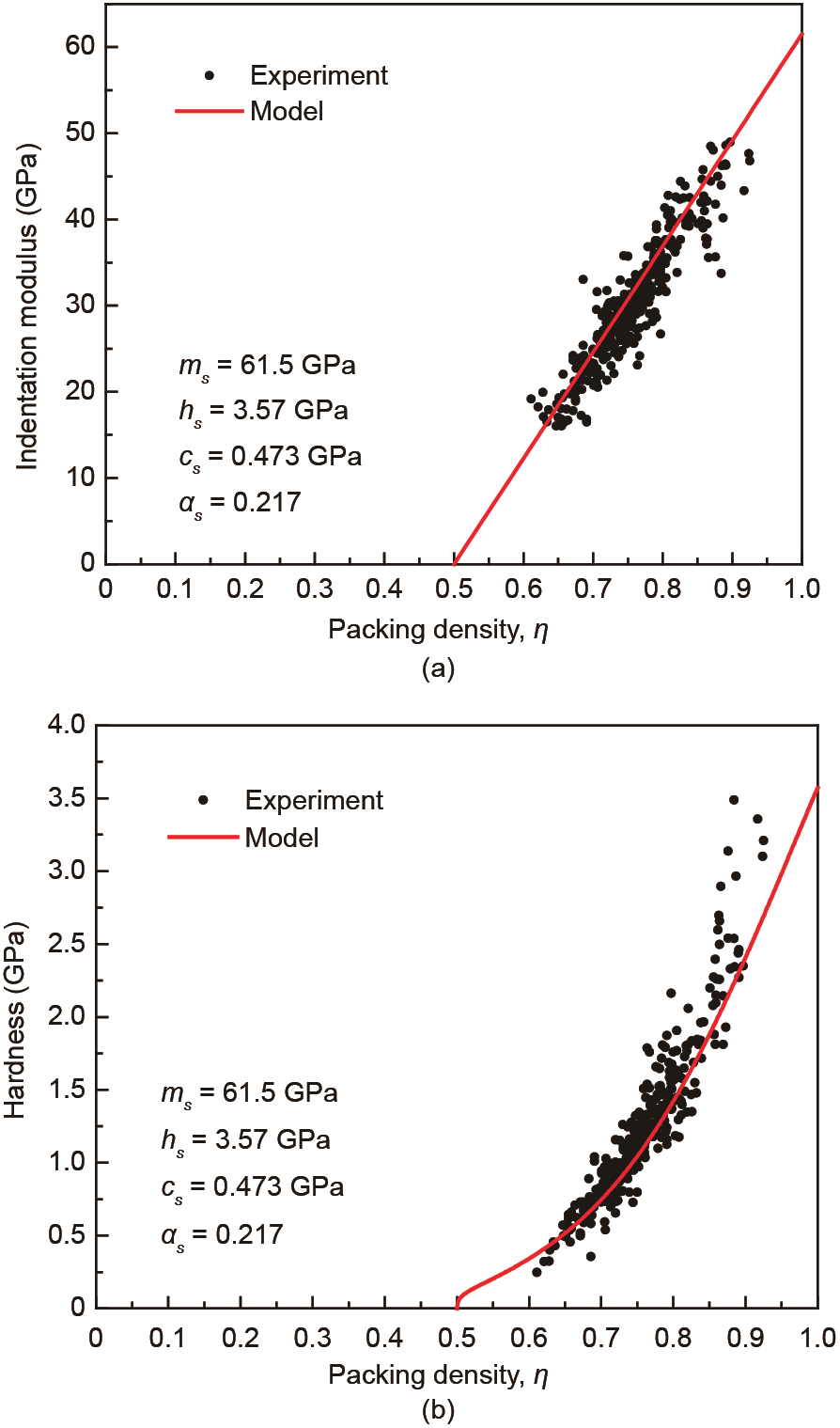
Fig. 10. Fitting results of indentation modulus/hardness-packing density of C–S–H gels.
However, the hardness of NCILD C–S–H was significantly higher than those of HD C–S–H and UHD C–S–H. The value of the hardness of NCILD C–S–H exceeded the theoretical maximum of the modeling. Fig. 11 shows the load–depth curves of HD C–S–H and NCILD C–S–H in the nanoindentation test. It can be seen that compared with HD C–S–H, the slope of the unloading part of the load–depth curve of NCILD C–S–H decreased, and the indentation depth of the indenter was significantly reduced under the same peak load. According to micromechanics, the indentation modulus is related to the bulk density η, solid’s Young’s modulus Es, and Poisson’s ratio vs. In addition, hardness is related to bulk density g, cohesion between solids cs, and friction coefficient αs. This indicates that the presence of nanofillers densifies the microstructures of LD C–S–H, rendering its packing density similar to that of HD C–S–H or UHD C–S–H. Moreover, the interaction (adhesion and friction coefficient) between basic building blocks in C–S–H gels is significantly enhanced by the addition of nanofillers.
《Fig. 11》

Fig. 11. Load–depth curves of HD C–S–H and NCILD C–S–H.
Based on an analysis of the packing density of NCILD C–S–H, the unique nanomechanical characteristics of NCILD C–S–H may be related to the existence of nano-core–shell elements (where the formation process of the elements is shown in Fig. 9). Fig. 12 shows a multiscale model of all types of hydration products. The modeling results reveal that the packing density of LD C–S–H (68.2% ± 2.5%) approximates the random limit packing density of spheres (64%). The packing density of HD C–S–H (74.5% ± 2.7%) corresponds to the densest packing of spheres (74%). In addition, hexagonal close-packed packing or ordered face-centered cubic packing, and the packing density of UHD C–S–H (81.3% ± 2.5%), are similar to the two-scale random limit packing density (87%) [44,51].
《Fig. 12》
Fig. 12. Multiscale model of all types of hydration products. ① Aggregate; ② outer hydration products (mostly LD C–S–H); ③ inner hydration products (mostly HD C–S–H and UHD C–S–H); ④ binder particle (including cement, fly ash, and silica fume); ⑤ outer hydration products (mostly NCILD D–S–H).
When nanofillers are incorporated, the packing mode of LD C–S–H changes from single- to multiscale packing because the particle size of nano-core–shell elements is greater than that of the basic building blocks in LD C–S–H gels. The change in packing mode increases the packing density of LD C–S–H and converts LD C–S–H into NCILD C–S–H. Because of the low content of nanofillers, the intrinsic properties (elastic modulus and Poisson’s ratio) of most basic building blocks in C–S–H gels are not significantly affected. Therefore, the indentation modulus of NCILD C–S–H is similar to that of HD C–S–H and UHD C–S–H when the packing density is similar. In addition, the presence of nano-core–shell elements enhances the interaction (adhesion and friction coefficient) between basic building blocks in LD C–S–H.
First, a greater number of basic building blocks exist around the nano-core–shell elements. The presence of nano-core–shell elements increases the force transmission range and reduces both the local stress concentration and the relative displacement between the basic building blocks. Second, the presence of nanocore–shell elements will hinder indenter indentation because it contains a hard nano-core derived from the pinning effect. Third, the difference between HD C–S–H (or UHD C–S–H) and NCILD C–S–H involves basic building blocks being replaced by nanocore–shell elements. From an energy perspective, this replacement increases the binding force between particles in the same volume. Therefore, higher energy is required to achieve the same depth. In other words, the pressing depth is shorter when the pressing force is the same. Therefore, the hardness of NCILD C–S–H was significantly higher than that of HD C–S–H and UHD C–S–H at the same packing density.
Fig. 13 shows a schematic of the nanoindentation test process for HD C–S–H and NCILD C–S–H. When the indenter is loaded, the molecular spacing between the basic building blocks increases with the penetration of the indenter, and the intermolecular force decreases until it disappears. When the indenter is unloaded, the displacements of the basic building blocks prevent the return to their original positions. According to the aforementioned analyses, when the indenter is pressed on the nano-core–shell element, the hardness, as determined from the experimental results, significantly increases as a result of the pinning effect. For 0-D nanofillers (i.e., nano titania and nanosilica), the probability that the indenter will simply press on the nano-core–shell elements is low owing to the small size of the nano-core–shell elements.
《Fig. 13》
Fig. 13. Schematic of nanoindentation test process of (a) HD C–S–H and (b) NCILD C–S–H.
By contrast, 2-D nanofillers (i.e., nano BN and multilayer graphene) can form nano-core–shell elements in a greater range. Therefore, the probability of detecting core–shell elements with 2-D nanofillers in a nanoindentation test is greater than with 0-D nanofillers. In this experiment, the content of NCILD C–S–H can generally be indicated by the geometrical size of the incorporated nanofillers (i.e., 2-D > 1-D > 0-D), which is highly consistent with the aforementioned analysis. This phenomenon may also indicate that the formation of nano-core–shell elements is the underlying mechanism of the formation of NCILD C–S–H.
《4. Conclusions》
4. Conclusions
This study investigated the effects of nanofillers on the nanomechanical properties of the ITZ in concrete by using a nanoindentation technique and SNT. The study also revealed the underlying mechanisms of nanofillers based on experimental results and micromechanical modeling. When the nanofillers were incorporated, the hydration degree of the ITZ increased, the contents of MPs and LD C–S–H in the ITZ decreased, and the contents of HD C–S–H and UHD C–S–H increased. These effects were attributed to the effects of nanofillers on the hydration process of the ITZ in concrete. The nanofillers could absorb ions in the fresh cement paste solution. The absorption of ions caused hydratable substance precipitation, hydration, and growth on the surfaces of nanofillers and finally formed numerous nano-core–shell elements. These effects can increase the degree of hydration of cement paste and improve the outer hydration products in cement paste.
In particular, a new phase called NCILD C–S–H characterized by a superior hardness of 2.50 ± 0.23 GPa and a similar indentation modulus to that of HD C–S–H or UHD C–S–H was identified in this study for the first time. The modeling revealed that the presence of nanofillers caused the packing density of LD C–S–H to approximate that of HD C–S–H or UHD C–S–H and significantly changed the interaction (adhesion and friction) among C–S–H gels owing to the formation of nano-core–shell elements, thus forming NCILD C–S–H and further improving the performance of the ITZ. These findings indicate the substantial modification effects of nanofillers on the ITZ at a nanoscale and thus aid in further understanding and controlling the performance of concrete modified with nanofillers.
《Acknowledgments》
Acknowledgments
The authors would like to thank the funding offered by the National Science Foundation of China (51978127 and 51908103) and the Fundamental Research Funds for the Central Universities (DUT21RC(3)039).
《Compliance with ethics guidelines》
Compliance with ethics guidelines
Xinyue Wang, Sufen Dong, Zhenming Li, Baoguo Han, and Jinping Ou declare that they have no conflict of interest or financial conflicts to disclose.


 京公网安备 11010502051620号


