

《1. Introduction》
1. Introduction
With the development of materials science [1–3], numerous artificial actuators have emerged and shown various life-like motions [4,5], bringing new hope for bioinspired robotics [6–9]. Flagella and cilia, motile appendages of cells, exist in lots of biological systems and undertake a wide range of functions (e.g., propulsion, feeding, and transport) [10–12], which have aroused great attention of bionic researchers. At present, it has been disclosed that flagella and cilia adopt quite different motion strategies to support their life activities [13]. Commonly, flagella propel themselves by chiral waveforms, such as 2D planar wave motion [14] and 3D helical wave motion [15,16]; while cilia acquire effective movement through 2D or 3D asymmetric beating [17,18]. To imitate these motions, scientists have developed many biomimetic actuators based on different driven mechanisms, such as magnetic-driven [19–22], electric-driven [23–26], light-driven [27,28], ultrasound-driven [29], and fluidic-driven [30,31]. Studies on these bionic systems have benefited extensive engineering applications, including but not limited to cargo manipulation [32,33], liquid operation [34], low Reynolds number propulsion [35], microfluidics [36–38], medical robots [39,40], and so forth.
With the understanding of the low Reynolds number hydrodynamics, diverse motion styles in nature are well understood and can be achieved via proper engineering design (e.g., the planar swing of slender filament [41], the rotating propulsion of helical structure [42,43], and the asymmetric beating of hair-like stimulusresponsive actuators [26,28,44–46]). However, an interesting fact in nature is that all these aforementioned motions of eukaryotic flagella/cilia (i.e., planar/helical waveform propulsion and 2D/3D asymmetric beating) are evolved from the same 9 + 2 biological structure [47–50]. However, it remains a big challenge to design an alone architecture to achieve all these extrinsic motions, due to the lack of a unified perspective and profound understanding of such complex internal structures and mechanisms. To date, we still cannot completely replicate the wisdom of nature, that is, starting from a common structure to evolve rich motion forms. This failure prevents bionics research from getting any inspiration from fascinating internal structures, and makes us less likely to establish a unified bionic principle for artificial flagella and cilia.
In this work, we investigate the inner structures and intrinsic driving mechanisms of flagella/cilia and find that their microtubules, according to the activation states of dynein, can be simplified to three functional regions and generate diverse motions with some specific driven strategies. Inspired by that, we propose a new design concept and correspondingly fabricate an all-in-one three-channel based tubular actuator through a rod-embedded casting process. Just as the same 9 + 2 structure can evolve diverse biological motions, the all-in-one tubular actuator is also able to realize a variety of 2D/3D flagellar/ciliary motions by sequencing the actuation of each channel. Additionally, we extend more asymmetric ciliary beating modes and further verify their effectiveness through the low Reynolds number propulsion tests. Combining theoretical analysis and experimental evidence, this study provides new insights for flagella/cilia-inspired artificial systems and offers a telling example of realizing bionics that focuses on internal biological mechanisms.
《2. Materials and methods》
2. Materials and methods
《2.1. The unified physical model for flagellar/ciliary intrinsic driven mechanisms》
2.1. The unified physical model for flagellar/ciliary intrinsic driven mechanisms
As illustrated in Fig. 1(a), flagella and cilia have the same 9 + 2 structure consisting of nine doublet microtubules (DMTs) and a central pair complex (CPC) [51]. Under the restriction of connexin, the dynein’s sliding between two DMTs finally leads to DMTs’ bending ((i) in Fig. 1(b)). Relying on this mechanism, every tiny section of flagella/cilia can independently move, and when such bending of DMTs is transferred from root to tail, external motions are eventually realized. To elucidate the intrinsic driven mechanisms and acquire a unified principle, we select one infinitesimal element of the continuous flagellum/cilium (defined as  ) for analysis. As in (ii) in Fig. 1(b), taking DMTs 8 and 9 in as an example, the bending can be seen as the motion caused by forces along the dyneins. Each dynein is assumed to have the same micro-force
  . And if there are m dyneins between DMT 8 and DMT 9 in , the total force between two DMTs can be represented as
  The force between two DMTs can be rewritten as
  (N = 1–9, and N + 1 denotes 1 when N = 9) with the direction pointing from DMT N + 1 to DMT N. The resultant force on the cross-sectional movement can be expressed as
  Such simplification allows us to discuss the driving mechanisms of different motions from the perspective of the cross-section. After extending along the body, the periodic cross-sectional movement forms the final external flagellar/ciliary motility. In one motion period, the changing magnitude and direction of
  are respectively expressed as
  and
and  . The final external motion Z can be described as

where  is the motion type;
  is the phase-transfer speed; s1, s2, ..., sn are the n size parameters of a certain motion type.
  can be broadly expressed as

where  and
and  are the angles between the force vector and positive direction of the x-axis and positive direction of the y-axis, respectively;
  ,
,  and
and  ;
;  and
and  are unit vectors in vertical and horizontal directions; R is the real number set.
This unified model indicates that the cross-sectional motion of flagella/cilia plays a leading role and their transmission along the slender body of flagella/cilia (with phase difference) determines external swimming styles. Based on such a fact, we investigate the driving mechanism of various flagellar/ciliary motions with the proposed unified model, and find that all of them can be seen as produced by three functional regions adopting different driving strategies (details in Figs. S1–S4 and supplementary text in Appendix A). For the planar wave motion of flagellum, dyneins on two DMT groups (DMTs 2–4 and DMTs 7–9) contribute to the bending motion through alternately activation and inhibition, and the horizontal motion component is restricted by o-SUB5-6 [47]. Thus, as shown in Fig. 1(c), we consider dividing nine DMTs into two driving regions (regions 1 and 2) and one restricted region (region 3). The alternate activation of the two driving regions supports the beating of flagellum, and under the restriction of region 3, movement is ensured in a quasi-plane. The helical wave motion of flagellum is caused by the sequential activation of dyneins on nine DMTs [48]. To simplify this process, three successively activated DMTs are seen as one driving region, then the sequential activation of such three independent driving regions will lead to the final motion (Fig. 1(d)). In 2D ciliary beating, the power stroke and recovery stroke (two processes of a complete motion cycle in the ciliary beating) are respectively dominated by two alternately activated driving groups (DMTs 1–4 and DMTs 6–8) [49]. Here, we divide 9 + 2 structure into three driving regions, specifically, the driving group with more DMTs is regarded as containing two synchronously activated/inhibited driving regions, and another driving group (with fewer DMTs) is the third driving region (Fig. 1(e)). As for 3D ciliary beating, two DMT groups (DMTs 2–4 and DMTs 6–8) are alternately activated, which respectively dominate the power stroke and recovery stroke [50], and the remaining dyneins on other DMTs are not activated. As a result, we consider dividing nine DMTs into two driving regions and one inactive region (Fig. 1(f)). The above analysis suggests that three functional regions, with different actuation strategies, can eventually produce rich motion forms (Fig. 1(g)).
《Fig. 1》

Fig. 1. Design principle. (a) Illustration of the 9 + 2 structure; (b) (i) illustration of the bending mechanism of DMTs in the 9 + 2 structure; (ii) according to the dynamic model, the resultant force of a tiny flagella/cilia (e.g.,  ) points from DMT N + 1 to DMT N from the cross-sectional view; (c) in the planar wave motion of flagellum, 9 + 2 structure are divided into three regions: two driving regions and one restricted region; (d) in the helical wave motion of flagellum, 9 + 2 structure are divided into three driving regions; (e) in the 2D ciliary beating, 9 + 2 structure are divided into two driving parts: one part contains regions 1 and 2, the other one contains region 3; (f) in the 3D ciliary beating, 9 + 2 structure are divided into three regions: two driving regions and one inactive region; (g) summary of the design principle: from three functional regions of the 9 + 2 structure to the all-in-one three-channel tubular actuator. DMT: double microtubule; CPC: central pair complex.
《2.2. Fabrication and characterization of the three-channel based tubular actuator》
2.2. Fabrication and characterization of the three-channel based tubular actuator
To illustrate the biological mechanisms and the proposed bionic concept, we fabricate an all-in-one tubular actuator with three independently addressable channels to replicate the abovementioned flagellar/ciliary motility. As shown in Fig. 2(a), the soft actuator is made of silicone rubber (Ecoflex 00–30, Smooth-On Inc., USA) through a rod-embedded casting process. In the pretreatment process, Ecoflex-A and Ecoflex-B are mixed with a ratio of 1:1, after stirring and outgassing under the vacuum condition, the homogeneous composite elastomer is obtained. Then, it is injected into a 3D-printed five-piece mold with three metal rods (~3 mm in diameter) embedded. After exposing the molds to air for 12 h, the cured three-channel soft actuator is demolded by removing the 3D-printed shells and the metal rods. Lastly, the tip end (point P) of the actuator is sealed with the new uncured Ecoflex 00–30 (~2 mm in thickness), and three channels (I, II, and III) on the other end are respectively attached to the connecting pipes and sealed with the uncured Ecoflex 00–30. The fabricated actuator has a length of 65 mm and three identical channels (~3 mm in diameter), marked size parameters are shown in Fig. 2(b), and specific values can be found in Table S1 in Appendix A.
The tubular actuator is actuated by a pneumatic pump system (Fig. 2(c) and supplementary text in Appendix A). Like the organization of DMTs in the 9 + 2 structure, the actuator’s three channels are parallel attached to each other (i.e., an integrated structure). When compressed air is injected along the soft channel, it will produce transverse bending due to the pressure imbalance, which is very similar to the passive microtubule’s bending under the combination of dynein’s movement and fixed connexin’s restriction. Such a biomimetic actuator, which is essentially consistent with the real biological structure, will be utilized to present the cross-sectional movement of diverse flagellar/ciliary motions in this manuscript.
《Fig. 2》
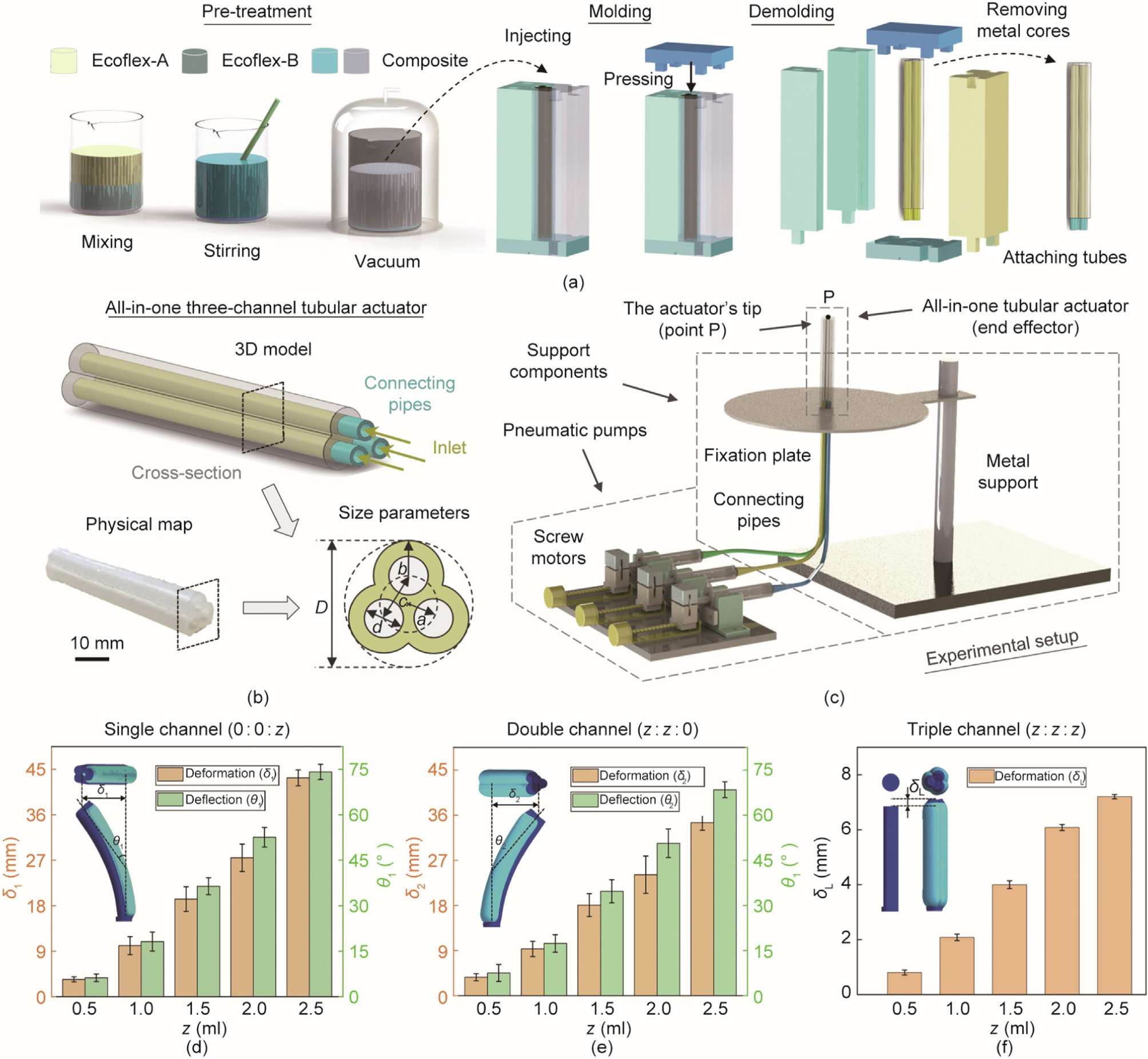
Fig. 2. Fabrication of the all-in-one three-channel tubular actuator, experimental setup, and the calibration of the actuator. (a) Illustration of the fabrication of the actuator: containing pre-treatment, molding, and demolding processes; (b) illustration of the three-channel tubular actuator and its size parameters; (c) illustration of experimental setup for the motion simulation; (d–f) calibration of the actuator’s bending (single channel, double channels, and triple channels). D: the diameter of the circumcircle of crosssection; a, b, c: the distances from tube center to channel center, from channel center to wall, and from channel center to channel center, respectively; d: the diameter of the channels; δ1, δ2: the horizontal deformation length; δL: the vertical deformation length; θ1, θ2: the deflection angle in the three types of pre-tests; z: air inflation volume.
The bending performance of the tubular actuator is calibrated by inflating the single channel, double channels, and triple channels. To describe it quantitively, we define the deformation length (δ1, δ2, and δL, where δ1 and δ2 are the horizontal deformation length; and δL is the vertical deformation length) and deflection angle (θ1 and θ2) in the three types of pre-tests, and acquire the changes of these parameters under different air inflation volume (z). As shown in Figs. 2(d)–(f), when the inflation volume varies from 0 to 2.5 ml, the variation ranges are δ1: 0–43.3 mm, δ2: 0– 34.0 mm, δL: 0–7.2 mm, θ1: 0–73°, and θ2: 0–68°. It suggests that the relative motion error is acceptable for the verification and demonstration of different motion styles. Notably, the errors here mainly come from two aspects: fabrication error of the actuator and mechanical error of the pneumatic pump system. Utilizing a fine manufacture technology and high-precision systems will effectively improve the motion accuracy. Especially, when biomimetic systems are used in small-scale manipulation devices (e.g., microfluidic systems), the requirements of precision motion control and stability are significantly crucial. In addition to the pneumatic actuation, the proposed design concept can also be performed by other actuation mechanisms. Specifically, the actuator is expected to be integrated and have independently controllable internal response units, which work together to show the unique and changeable external motion. Similar examples, such as liquid crystalline elastomer (LCE) based and hydraulic driven artificial cilia actuators [27,45], well conform to the point. Our design principle and driving strategies are also expected to be used in the bionic systems with the abovementioned characteristics and bring rich motion styles to them. Other details of the all-in-one tubular actuator can be found in Fig. S5 and supplementary text in Appendix A, including kinematic analysis, finite element method (FEM) simulation, and trajectory tracking.
《3. Results and discussion》
3. Results and discussion
《3.1. Reproduction of the 2D/3D flagellar/ciliary motility in nature》
3.1. Reproduction of the 2D/3D flagellar/ciliary motility in nature
The three-channel based tubular actuator can reproduce all the flagellar and ciliary motions in nature (i.e., the planar/helical wave motion of flagella and the 2D/3D beating motion of cilia). For the planar wave motion of flagellum, we alternately inflate/deflate channels I and II with the inflation volume range of 0 to  (the peak value = 2.5 ml), while keeping the channel III synchronously providing restrictions for channels I and II to correct the bending direction (Fig. 3(a)). By giving a proper inflation ratio (channel I/II: channel III = 4:3, Fig. S6 and supplementary text in Appendix A), a planar curved trajectory is obtained (Fig. 3(b) and Video S1 in Appendix A), which is consistent with the cross-sectional motion of the planar waveform in flagella. On the other hand, for the helical wave motion of flagellum, we inflate the three independent channels in turn (I–II–III) with the same phase difference (2π/3) and peak volume () (Fig. 3(c)). The actuator presents a nearly circular trajectory which well reproduces the crosssectional motion of the helical wave motion (Figs. 3(d) and (e), and Video S1). Here, it is noticed that the cross-sectional motions of flagella (either planar or helical wave motion) are reciprocal, and therefore they cannot independently provide effective propulsion. Yet, such cross-sectional motion can be transmitted along the slender body to form an effective 2D/3D chiral propulsive wave (cross-sectional motion with multi-periods) as the real biological motions observed in nature.
《Fig. 3》

Fig. 3. The flagellar cross-sectional motion simulation through the all-in-one actuator. (a) Schematic diagram and inflation strategy for the actuation of planar wave motion; (b) along the actuator, the cross-sectional motion of planar wave motion forms an in-plane beating; (c) schematic diagram and inflation strategy for the actuation of helical wave motion; (d) along the actuator, the cross-sectional motion of helical wave motion forms a nearly circular path in 3D-space and its motion process; (e) the recorded trajectories at different times (top view and front view). t: time; T: the time of a complete beating cycle.
An entire motion cycle of 2D ciliary beating consists of one power stroke and one recover stroke with different paths (i.e., path asymmetry) [18]. Following the driving strategy in Fig. 4(a), we firstly inflate channel III to a volume of as the initial state (Fig. 4(b)). Then, in the power stroke, channels I and II are inflated to synchronously (stage 1: 0–T/4, where T is the time of a complete beating cycle) followed by deflating channel III to zero (stage 2: T/4–T/2) to generate the power stroke. In the recovery stroke, channels I and II are deflated to zero (stage 1: T/2–3T/4), and then channel III is refilled to (stage 2: 3T/4–T) to produce the recovery stroke. As the tip trajectory shown in Fig. 4(c) and Video S1, the three-channel based tubular actuator well exhibits the 2D ciliary beating with path asymmetry. In the 3D ciliary beating motion, the mean axis of the trajectory is tilted away from the surface normal, presenting the orientational asymmetry [17]. To replicate such 3D beating motion, we alternately inflate/deflate channels I and II while maintaining channel III without inflation (Fig. 4(d)). In this case, as the result shown in Fig. 4(e), it presents an eccentric trajectory relative to the bottom center point (point B) in the top view (Fig. 4(f) and Video S1), well exhibiting the orientational asymmetry in 3D ciliary beating motion. Unlike flagellar wave motions, the cross-sectional motions of both 2D and 3D ciliary beating are non-reciprocal, which is consistent well with the asymmetric motion features observed in natural cilia.
《Fig. 4》
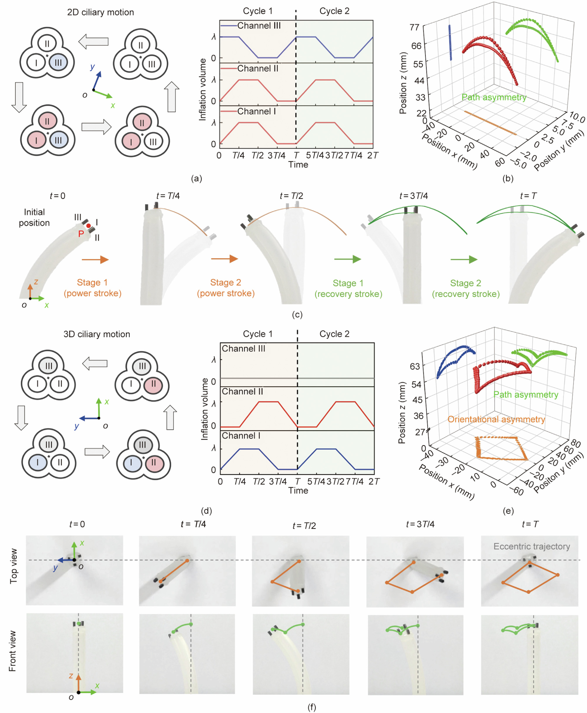
Fig. 4. The cross-sectional motion simulation of 2D/3D ciliary beating through the all-in-one actuator. (a) Schematic diagram and inflation strategy for the actuation of 2D ciliary motion; (b) along the actuator, its cross-sectional motion forms an in-plane motion with path asymmetry; (c) different stages in the power stroke and recovery stroke of 2D ciliary motion (front view); (d) schematic diagram and inflation strategy for the actuation of 3D ciliary motion; (e) along the actuator, its cross-sectional motion forms an out-of-plane motion with orientational asymmetry; (f) different stages in the power stroke and recovery stroke of 3D ciliary motion (top view and front view).
《3.2. Extended symmetry-breaking ciliary beating modes》
3.2. Extended symmetry-breaking ciliary beating modes
The internal driven mechanisms inspired tubular actuator can also derive lots of unreported driving strategies just as the 9 + 2 biological structures can evolve rich motion modes. As illustrated in Fig. 5(a), the original 2D ciliary beating is evolved from two alternately driven groups, while the original 3D beating is realized by the sequenced actuation of three channels. Realizing such facts, we infer that a variation in the inflation of the actuator’s three channels would derive new beating modes, because these changes will introduce new asymmetry to the system. To demonstrate the effectiveness of this strategy in extending new types of ciliary beating, we simply select a channel (channel III) keeping zero in the original 3D ciliary beating to vary its inflation volume by setting a constant volume, higher peak volume, and lower peak volume, which are labelled as type A, type B, and type C, respectively.
For type A beating motion, we change the actuator’s channel III from zero to a constant inflation volume (blue line) in the whole motion cycle, while keeping other parameters without change (i.e., channels I/II alternately inflate/deflate within the inflation volume range of 0–) (Fig. 5(b)). As the results shown in Fig. 5(c) and Video S2 in Appendix A, the new actuation style destroys the consistency of bending deformation towards each direction, which leads to the path asymmetry (front view) and orientational asymmetry (top view), extending a new type of 3D ciliary beating. For type B and type C beating motion, we vary the peak inflation volume of channel III (type B: 1.2, red line; type C: 0.5, green line) while keeping the other two channels with the peak volume of and alternately inflate/deflate three channels, as illustrated in Fig. 5(d). Similarly, the variation in the peak inflation volume also leads to asymmetric properties and produce new types of ciliary beating, which simultaneously holds the orientational asymmetry (eccentric trajectories in the top view) and path asymmetry (front view), as shown in Fig. 5(e) and Video S2.
《Fig. 5》
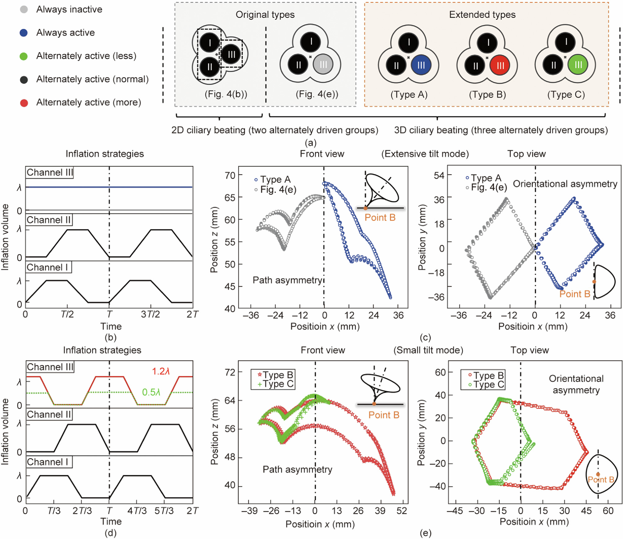
Fig. 5. Extended strategies for bionic ciliary beating based on the proposed engineering platform. (a) Proposed driving strategies: original types and extended types; (b) inflation strategies of original type and type A 3D ciliary beating: channels I and II are alternately inflated (peak inflation: ) and channel III is with constant inflation volume (0 or ); (c) the actuator achieves both path asymmetry (front view) and orientational asymmetry (eccentric trajectory, top view) with an extensive tilt mode; (d) inflation strategies of type B and type C 3D ciliary beating: three channels are alternately inflated (peak inflation of channels I and II: ) with the peak inflation of channel III adjusted to 1.2 (more) or 0.5 (less); (e) the actuator achieves eccentric trajectories both path asymmetry (front view) and orientational asymmetry (eccentric trajectory, top view) with a small tilt mode.
In type A ciliary beating, the tip trajectory tilts only one side of the central axis and the bottom center (point B in Fig. 5(c)) is on the boundary of the trajectory. Such characteristic is similar to the original 3D ciliary beating, which is represented as extensive tilt mode [17]. However, due to the different constant inflation volume in channel III ( for type A and 0 for original type), their tip trajectories are biased to contrary sides of the central axis, and type A ciliary beating envelops a larger area by comparison (front view in Fig. 5(c)). On the other hand, type B and type C ciliary beating demonstrate a totally different characteristic from the original ones. Rather than on one single side, their tip trajectories distribute on both two sides of the central axis and the bottom center point B is enclosed by the trajectories (Fig. 5(e)), which is named small tilt mode [17]. Moreover, caused by the different peak inflation volume (1.2 for type B and 0.5 for type C), type B envelops a larger area (front view in Fig. 5(e)) compared with type C, which further enriches the diversity. It’s worth noting that these three new motion types are only a few examples for demonstrating the effectiveness of the proposed extension strategy. Actually, more motion types can be created by introducing more changes into the threechannel tubular actuator, such as inflation speed, varied inflation cycles in three channels, and so forth. It suggests that introducing the asymmetric feature could be a general approach to derive new actuation strategies for a wide spectrum of responsive-materialbased artificial cilia systems, which is consistent well with the current physical understanding of biological cilia [18] and some novel concepts of bionic design [20,21,31,45].
《3.3. Demonstration of the diverse propulsion modes at low Reynolds number》
3.3. Demonstration of the diverse propulsion modes at low Reynolds number
To intuitively exhibit the effectiveness of the abovementioned flagellar/ciliary motions, we carry out a series of propulsion tests at low Reynolds number environment. Here, the tubular actuator is immersed in silicone oil and actuated by inflating air into the three channels following the abovementioned actuation strategies. Then, the movement of red-marked fluids (below the tip) is recorded to evaluate the propulsion effectiveness. In these experiments, the estimated Reynolds number Re = = 0.014, where
  is the length of the actuator (65 mm),
  is the actuation frequency of the actuator (1/30 Hz), and
  is the kinematic viscosity of silicone oil (10 000 cSt, 1 cSt = 1 mm2 ·s–1 ). More details about the experimental setup can be found in supplementary text in Appendix A.
The recorded propulsion results of five types of ciliary beating are shown in Fig. 6, containing the initial position (in red), intermediate process (in gray), and final position (in blue). Briefly, all of them can contribute to effective fluid propulsion at low Reynolds number. Specifically, in the original 2D ciliary beating, a swept area is formed through the different paths of the power stroke and recovery stroke, which induces a leftward shift (~8.5 mm) of the red-marked region after 12 cycles (Fig. 6(a) and Video S3 in Appendix A). For the 3D ciliary beating, effective propulsion is achieved by the orientational asymmetry, which will lead to a net displacement to the eccentric direction of trajectories. As shown in Figs. 6 (b)–(e) and Video S3, after 12 cycles, original 3D type and types A– C ciliary beating respectively propel the marked fluid to move 8.9, 10.1, 17.0, and 14.6 mm. The relatively small propulsion effect of the original 3D type and type C compared with the other two presents consistency with the difference in tip trajectories recorded before. Besides, the original 3D ciliary beating and type C ciliary beating show both propulsion and mixing effects (Figs. 6(c) and (e)), which may be due to the marked fluid here positioned inside both the propulsion region and mixing region (details in Fig. S7 and supplementary text in Appendix A). The above results verify the effectiveness of biomimetic ciliary beating for propulsion at low Reynolds number environment. However, different from the asymmetric ciliary beating, it’s worth noting that the cross-sectional motions of flagella cannot directly propel the fluids (Figs. S8 and S9, supplementary text, and Video S3 in Appendix A) because their symmetrically reciprocating swing (planar wave motion) and rotation (helical wave motion) are restricted by Stokesian-hydrodynam ics-governed physical laws. To achieve the effective propulsion, a slender tail is required for flagella to transfer the cross-section motion along the body to form chiral waves.
《Fig. 6》

Fig. 6. Low Reynolds number propulsion tests of the actuator. (a) Illustration of original 2D ciliary beating test; (b) illustration of original 3D ciliary beating; (c–e) illustration of the type A, type B, and type C 3D ciliary beating. In above experiments, main motion properties and propulsive direction are shown in the sketch map. Meanwhile, cycles 0– 12 of experiments are recorded with an interval of three cycles, among these demonstrations, initial position, intermediate process, and final position are respectively marked in red, gray, and blue.
《3.4. Discussion》
3.4. Discussion
Herein, understanding the mechanism of how the same biological structure evolves diverse motion styles provides inspiration for designing artificial flagellar/ciliary systems. As shown in Table 1, compared with previous studies [7,19–25,27,33,34,41,42,44–46], the fabricated actuator, inspired by the intrinsic mechanisms, achieves the unprecedented integration of the main flagellar/ciliary motions. At the mechanism level, we provide universal design and actuation strategies to expand the existing bionic mechanism [13,18,52]. Even though the derived bionic actuator can still not wholly reproduce the precise biological structures, it exactly helps us intuitively understand what happens inside the flagella/cilia and may bring inspiration to the microtubule grouping strategies of 9 + 2 or 9 + 0 structures in motile cilia. At the level of bionic actuator, the proposed actuator has significant independent addressability (like several previous cilia-inspired actuators [30,31,45]); further, when expanded to more actuators, rich motions make them an excellent engineering platform for theoretical research to understand the phenomena and principles in biological systems (e.g., hydrodynamics of multi-motions interaction). Taken overall, the proposed all-in-one actuator deepens our understanding of flagellar/ciliary propulsion, enriches the biomimetic system design, and provides a feasible approach for exploring the physical mechanisms of biological systems.
《Table 1》
Table 1 Comparison of current artificial systems inspired by flagella and cilia.
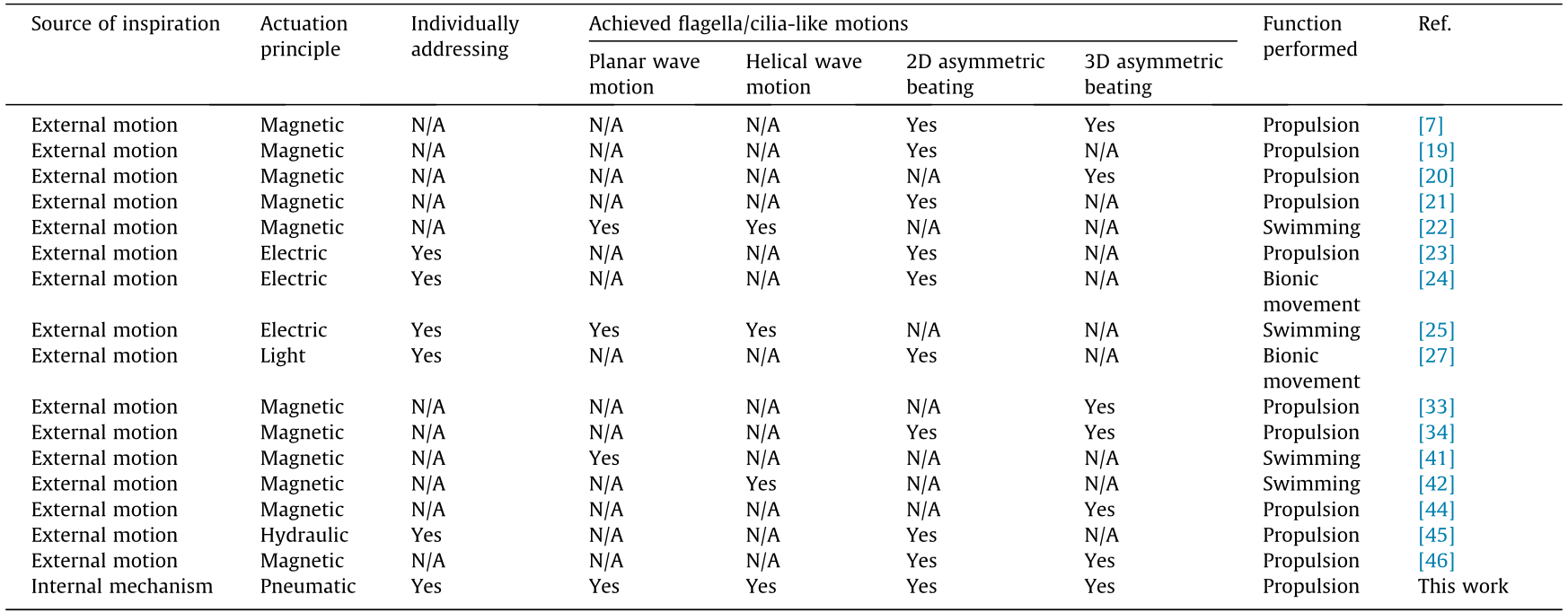
N/A: not applicable.
《4. Conclusions》
4. Conclusions
The common 9 + 2 structure of flagella and cilia, as an excellent entry point, provides us the chance to imitate multiple flagellar/ciliary motion forms within one biomimetic design. By investigating the intrinsic driven mechanisms of diverse flagellar/ciliary motions, we propose a unified physical model, and further simplify the complex biological structure and intrinsic driving strategies. We conclude that various flagellar/ciliary motions can be regarded as actuated by three functional regions through different driving strategies. Inspired by that, we correspondingly fabricate an allin-one three-channel tubular actuator to replicate planar/helical flagellar wave motion and 2D/3D asymmetric ciliary beating. Based on the proposed engineering platform, we expand more driving strategies for mimicking the different modes of 3D ciliary beating. The effectiveness of proposed biomimetic motions is finally verified through the low Reynolds number propulsion experiments. To sum up, this study provides a new design concept and general driving strategies for the development of biomimetic flagella/ cilia-based systems and explores the bionics inspired by the intrinsic actuation mechanisms.
《Acknowledgments》
Acknowledgments
This work was support by the Shenzhen–Hong Kong–Macao Science and Technology Project (Category C) sponsored by the Science Technology and Innovation Committee of Shenzhen Municipality (SGDX20201103093003017), Shenzhen Key Basic Research Project (JCYJ20200109114827177), and Hong Kong RGC General Research Fund (CityU 11216421).
《Compliance with ethics guidelines》
Compliance with ethics guidelines
Jiaqi Miao, Tieshan Zhang, Gen Li, Dong Guo, Siqi Sun, Rong Tan, Jiahai Shi, and Yajing Shen declare that they have no conflict of interest or financial conflicts to disclose.
《Appendix A. Supplementary data》
Appendix A. Supplementary data
Supplementary data to this article can be found online at https://doi.org/10.1016/j.eng.2022.09.014.


 京公网安备 11010502051620号


