
《1. Introduction》
1. Introduction
Chlorophenols (CPs) are quantitatively significant pollutants released into the environment by chemical and pharmaceutical industry activities. They are also by-products of industrial processes in the manufacturing of polymers, dyes, textiles, resins, and explosives. CPs and their derivatives are mutagenic, carcinogenic, and immunogenic for humans and other organisms, and their treatment, disposal, and management have become serious challenges to stakeholders and health sectors. Most types of CPs are refractory to microbial degradation, making it imperative to develop more efficient methods for minimizing their pollution in water environments and ecological systems. Electrochemical oxidation has drawn increasing research interest for decentralized water decontamination because the application of electrons as traceless reactants offers several unique advantages, such as high efficiency, cleanliness, process integration, and ease of automation [1–3]. Electrochemical oxidation leads to the destruction of CP pollutants via direct electron transfer (DET) and indirect oxidation mediated by ·OH produced by water electrolysis.
Because low-concentration CPs can be oxidized faster than they can be transported to the anode surface, electrochemical oxidation of CPs is commonly controlled by diffusion. Reactive electrode membranes (REMs) offer a promising alternative for improving mass-transfer efficiency by flow-through electrolysis [4,5]. Compared with mechanical agitation and flow-by operations, REMs can conduct electrolysis in the flow-through mode with convection-enhanced mass transfer [6]. Thus, membrane electrodes show great promise for potential applications in water purification, such as pollutant removal, self-cleaning membrane, resource recovery, and seawater desalination [7–9].
Most studies on REMs are performed at the laboratory scale under well-controlled conditions. Consequently, a gap remains between experimental studies and practical applications. The process of scaling up a reactor from a lab prototype to an industrial plant is often referred to as the ‘‘Valley of Death,” and there is no straightforward method that guarantees success in the scale-up of membrane electrodes. Unlike conventional chemical and biochemical reactors, where the geometric, kinematic, and thermal features are similar between the model and practical units, the electrode configuration of REMs is of prime importance [2,10,11]. Most flow-through electrochemical reactors are configured for plug-flow filtration [12,13] based on two parallel plate electrodes (PPEs) made of porous conductive materials, such as carbon nanotubes (CNTs) or Ti4O7 [14,15]. Although this mode provides a convenient and easy-to-handle platform to test the performance of electrode materials, challenges remain to scale up the electrochemical setup because increasing the electrode spacing or reactor volume increases the ohmic resistance and decreases the area-tovolume ratio. Hence, there is a compelling need to develop more efficient, reliable, and scalable electrode configurations to enable well-engineered industrial applications.
In principle, the appropriate electrode configuration should ① have a reasonable electric field distribution and low ohmic resistance, ② be effective for the removal of CP pollutants, and ③ allow modularization for easy-to-handle scale-up and engineering applications. Tubular electrodes with a cylindrical geometry are more favorable for increasing current density and power generation in energy conversion systems, such as solid oxide fuel cells (SOFCs), polymer electrolyte membrane fuel cells (PEMFCs), and vanadium redox flow batteries (VRFBs) [13,16–18]. Inspired by these successful applications, we attempted to bridge the ‘‘Valley of Death” for scaling up REMs by developing a tubular concentric electrode (TCE) configuration for the engineered application of electrochemical CPs removal.
In this study, we developed a TCE configuration containing an inner titanium suboxide (TiSO) tube (ceramic membrane anode) and outer stainless-steel (SS) tube (cathode), which allows the wastewater stream to flow through the two tubes in either the anode-to-cathode (AC) or cathode-to-anode (CA) direction. The tubular TiSO was selected as the anode material because its conductivity approaches that of metals, and its corrosion resistance is close to that of ceramics. The unique advantages of high conductivity, good stability, high oxygen evolution potential, and low cost make it a promising anode material for water purification [19]. First, we investigated the electric field distribution for different electrode configurations using software simulation and electrochemical validation. Second, we tested the electrochemical removal of typical biorefractory CP pollutants (i.e., 2,4- dichlorophenol (2,4-DCP)) under AC and CA flow modes, and the relevant mechanisms were elucidated using theoretical calculations and experimental data. Finally, we proposed a numberingup strategy for scaling up the TCE module and flow-through reactor and tested its suitability for engineered water decontamination in single-pass mode. The primary objective of this study was to determine a reasonable electrode configuration for the scale-up of the REM reactor for CP pollutants removal.
《2. Materials and methods》
2. Materials and methods
《2.1. Materials》
2.1. Materials
All purchased reagents were of analytical grade if there is no special statement and used without further purification. Sodium perchlorate (NaClO4), 2,4-DCP, and chromatographic-grade methanol were purchased from Sinopharm Chemical Reagent Co., Ltd. (China), and the solution was prepared using ultrapure water obtained from a Milli-Q system (18.2 MΩ·cm at (22 ± 1) °C). The TiSO electrode was designed and manufactured according to the procedures described in our previous study [19].
《2.2. Experimental setup and operation》
2.2. Experimental setup and operation
The electrolysis experiments were conducted in a Plexiglas cylindrical electrolytic cell with a total volume of 3.8 L (220 mm × Φ 150 mm) at room temperature ((25 ± 1) °C). The cell contained a tubular TiSO anode (outer diameter, 30 mm; thickness, 3 mm; length, 143 mm; projected area, 132.9 cm2 ) and a SS cathode (140 cm2 ). The electrodes were connected to a direct current (DC) power supply by copper wires. Prior to the tests, the TiSO electrodes were cleaned for 10 min in a 0.5 mol·L-1 NaClO4 solution at a current density of 30 mA·cm-2 . The initial influent contained 0.1 mol·L-1 NaClO4 and 10 mg·L-1 2,4-DCP at a neutral pH (7.2 ± 0.2), and the electrolytic cell was operated in single-pass mode without recirculation. The experiments were performed with 10 min of stabilization without the application of current, and 5 mL aliquots were withdrawn from the effluent at specified intervals, followed by immediate filtration with cellulose acetate filters (0.22 μm) before chemical analysis.
The hydraulic retention time (HRT, s) of the system was calculated by

where J (m·s-1 ) is the permeation flux, d (m) is the thickness of a single TiSO anode, A (m2 ) is the anode area, and Q (m3 ·s-1 ) is the flow rate.
《2.3. Electrochemical characterization》
2.3. Electrochemical characterization
Electrochemical characterization was performed with a SS counter electrode and Ag/AgCl (saturated KCl aqueous solution (KClaq), 0.198 V vs standard hydrogen electrode (SHE)) reference electrode. Cyclic voltammetry (CV) was performed at a sweep rate of 100 mV·s-1 in a three-electrode cell in the 2,4-DCP degradation phase. Electrochemical impedance spectroscopy (EIS) was conducted between 10 mHz and 100 kHz using a sinusoidal potential perturbation with an amplitude of 5 mV.
《2.4. Analyses》
2.4. Analyses
The 2,4-DCP concentration was determined using a ultrahighperformance liquid chromatography (UPLC) instrument (Agilent 1200, USA) equipped with a photodiode array detector (PDA) and a reversed-phase C18 column (50 mm × Φ 2.1 mm, Waters, USA). The mobile phase consisted of water/methanol (30:70, v/v) at a flow rate of 0.1 mL·min-1 . The degraded intermediates of 2,4-DCP were analyzed qualitatively based on the mass-to-charge ratio using UPLC with electrospray ionization mass spectrometry (UPLC–ESI/MS) (Agilent 6460, USA) with mobile phase A (ultrapure water) and B (chromatographic-grade acetonitrile). Highresolution mass spectra were collected for range of the mass-tocharge ratio (m/z) 80–220 using negative continuum mode with a scanning time of 0.15 s, and the suspected intermediates were fragmented in the collision cell. The ionization source was set up with a capillary voltage of 3 kV, temperature of 200 °C, and desolvation temperature of 550 °C. The samples (20 μL) were analyzed in duplicate to ensure the accuracy and repeatability of the mass spectroscopy measurements. Chemical oxygen demand (COD) was determined using an LH-3BA spectrophotometer (Lianhua Technology Co., Ltd. (China), chemical reagent type number: LHD/E).
Energy consumption normalized per order (EEO) of contaminant was calculated by Ref. [20]:
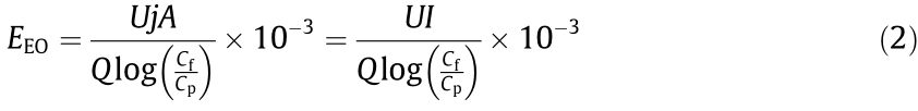
where EEO (kW·h·m-3 ) is the volumetric energy consumption required to reduce the organic contaminants by one order, U (V) is the average cell voltage; j (mA·cm-2 ) is the current density, I (A) is the current, and Cf (mg·L-1 ) and Cp (mg·L-1) are the feed and permeate concentrations, respectively.
The current efficiency for oxidation was calculated by
where CODf (mg·L-1 ) and CODp (mg·L-1 ) are the COD concentrations of the feed and permeate, respectively, b (4) is the stoichiometric coefficient for number of electron transfer, F is the Faraday constant (96 485 C·mol-1 ), V (L) is the volume treated over duration t, and  is the equivalent molar mass of oxygen (32 g·mol-1 ).
《2.5. Electric field simulation》
2.5. Electric field simulation
Simulations were conducted on the PPE, tubular/planar electrode (TPE), and TCE configurations using COMSOL Multiphysics software (version 5.5; Palo Alto, USA). The models were used to simulate the electric field distribution for different electrode configurations using the definition of electric field strength:

where E is the electric field strength, and φ is the electric potential.
《2.6. Theoretical calculations》
2.6. Theoretical calculations
Density functional theory (DFT) calculations were conducted using Gaussian software. The activation energy (Ea, kJ·mol-1 ) for DET oxidation as a function of electrode potential was calculated according to Marcus theory. The calculation for the DET reduction reaction is similar and not shown.
where  (kJ·mol-1 ), which reflects the total reorganization energy for the electron-transfer oxidation reaction, can be calculated by subtracting
  (kJ·mol-1 ) of the reactant from that of the product with the same geometry. E (V) is the electrode potential vs SHE, and E0 (V) is the standard potential of the DET reaction of the reactant, which can be determined thermodynamically as

where  (kJ·mol-1 ), which represents the free energy of reactant oxidation, can be calculated using the DG0 determined from the optimized geometric structure of the reactant and product. n (n = 1) is the number of transferred electrons, and
  is the reference absolute standard potential of the SHE (4.28 eV). The calculations were performed according to procedures described in previous studies [6,21].
《3. Results and discussion》
3. Results and discussion
《3.1. Electric field distributions of different electrode configurations》
3.1. Electric field distributions of different electrode configurations
The spatial distribution of the electric field significantly affects electrochemical reactions because it is closely linked to charged ion transport [13,22–25]. In other words, electrochemical reactions only occur in the region of the electrode surface where the electric field lines reach, and vice versa. Because the electric field distribution is closely related to the electrode configuration, we used COMSOL modeling to visualize and quantitatively analyze the electrostatic field of three typical electrode configurations for wastewater treatment [13]: PPE, TPE, and TCE. As shown in Fig. 1, the symmetric PPE and TCE configurations exhibited the most uniform electric field distributions, whereas an asymmetric electric field was observed for the TPE configuration, which is similar to the results found by Hankin et al. [23] in a photoelectrochemical reactor and Sun et al. [26] in an electrochemical reactor [26]. This clearly suggests that complete utilization of the anode area could be achieved with the PPE and TPE configurations. However, less than 1/3 of the area of the tubular anode was active for the TPE configuration because the equipotential lines are always perpendicular to the electric field at each of their crossings. The electric field points away from the anode plane and toward the cathode plane. Because the charges are equal and opposite, the electric fields sum in the interpolar region, whereas they cancel each other out to zero in the region outside of the two electrodes [26]. In other words, only the electrode surfaces normal to each other are electrochemically active, and no transformation occurs in other regions. This can be easily visualized experimentally by observing the electrodeposition of a Cu film on only the front side of an SS disc (Fig. S1 in Appendix A). Note that the small amount of Cu film deposited at the edges of the back side was caused by the molecular diffusion of Cu2+ under a concentration gradient.
《Fig. 1》

Fig. 1. COMSOL simulations of the electrostatic field for the (a) PPE, (b) TPE, and (c) TCE configurations with front and sectional views; (d) optical image of the TCE module.
For the same anode, the cathode geometry can have a significant impact on the electric field distribution. Clearly, a uniform interelectrode electric field distribution is essential to effectively utilize the electrochemically active area because the ions can diffuse along the field lines, which has been proven to be efficient for water disinfection [24]. These results suggest that when designing a flow-through electrolytic cell, the surface of the electrode should be orthogonal to the electric field lines everywhere to maximize the effective electrochemically active area of the electrode. In accordance with this principle, the PPE design is more suitable for plug-flow electrolysis, whereas the TCE design is more rational for encompassed-flow electrolysis.
《3.2. Dependence of ohmic resistance on electrode configuration》
3.2. Dependence of ohmic resistance on electrode configuration
When the anode is polarized by passing current through the electrolytic cell, the voltage drop U (V) is determined by the equilibrium potential difference and overpotential [27]:

where Umin (V) is the theoretical minimum voltage required for electrolysis, ηA (V) is the activation overpotential dependent on a suitable catalyst, ηD (V) is the diffusion overpotential due to concentration polarization, and ηohm (V) is the ohmic overpotential caused by the electrode material, configuration, and electrolyte [27]. For a given electrolytic system under flow-through operation, gohm is the dominant contributor to the cell voltage and thus energy consumption under constant-current electrolysis. Herein, the ohmic overpotential is calculated according to Ohm’s law:

where  is the sum of the ohmic resistances.
It is worth noting that the electrode configuration may have a significant impact on the magnitude of the ohmic resistance. For example, based on an identical anode diameter (29 mm), axial length (142 mm), and electrolyte (0.1 mol·L-1 NaClO4, pH 6.5), the  value of the TCE configuration (2.1 Ω) was 89.3% and 83.3% lower than those of the PPE (19.8 Ω) and TPE (12.6 Ω) configurations, respectively, according to the x-intercept in the Nyquist plot of the EIS data (Fig. 2(a)). This difference could result from the difference in ion transport in the electrolyte in the interpolar space for the two systems. For the PPE configuration, the ohmic resistance is positively proportional to the axial length of the reactor, as follows:

where κ (S·m-1 ) is the specific conductivity of the interpolar electrolyte, L (m) is the axial length of the tubular reactor, A (m2 ) is the electrode area, and r (m) is the electrode radius. According to Eq. (9),  is a function of L, κ, and r. Therefore, if κ and r are known constants, is only a function of L. That is, the ohmic resistance of the PPE configuration is considerably more sensitive to the scale of the reactor, and scaling up the electrolytic cell by increasing the axial length of the tubular reactor will lead to a linear increase in the ohmic resistance. In contrast, when r1 and r2 are fixed, the ohmic resistance of the TCE configuration is inversely proportional to L, suggesting that increasing the axial length of the cell adds value by lowering the ohmic loss (Eq. (10)) and energy consumption (Eq. (2)), rather than the inverse.

where r1 is the radius of the tubular anode, and r2 is the radius of the tubular cathode.
Despite minor differences in values between the PPE and TCE configurations in small lab-scale prototype cells, scaling up these two configurations would lead to opposite behaviors of their values with increasing reactor volume (Figs. 2(b) and (c)). The decreased ohmic resistance of the TCE system becomes more significant when the conductivity of the solution is low (e.g., domestic sewage and groundwater) [28]. As shown in Fig. 2(d), the calculated value of the PPE configuration was 16 times that of the TCE configuration when the axial length of the tubular reactor was increased from 1 to 14 cm (Eqs. (9) and (10)). The TCE configuration was compact with a small electrode spacing and large electroactive area, considerably enhancing electron transfer and lowering the internal resistance [29].
《Fig. 2》

Fig. 2. EIS spectra for (a) different electrode configurations and (b) PPE and (c) TCE tubular reactors with various axial lengths; (d) total internal resistance () as function of TCE length.
Together, the combination of experimental results and theoretical verification demonstrate that the TCE configuration is more favorable for scaling up REMs owing to its uniform electric field and low ohmic resistance. Similarly, Lei et al. [30] reported efficient phosphate recovery (> 50 %) using a scalable prototype with a tubular SS cathode in a columnar electrochemical reactor over 173 days. The unique advantages of the amplified TCE configuration enabled the application of a scaled-up membrane electrode system [31]. Next, we shifted our focus to the engineered application potential of the TCE system for wastewater treatment.
《3.3. Electrochemical removal of 2,4-DCP by the REM module》
3.3. Electrochemical removal of 2,4-DCP by the REM module
The electric field between the anode and cathode in the TCE configuration exhibited a uniform distribution, suggesting that efficient faradaic reactions occurred. The stream flow sequence, upstream from the anode to the cathode (AC mode) or downstream from the cathode to the anode (CA mode), has a crucial impact on the electrochemical reactions. Thus, we examined a tubular concentric TiSO anode/SS cathode REM reactor for the electrochemical removal of 2,4-DCP (10 mg·L-1 ) with a NaClO4 (0.1 mol·L-1 , pH 6.5) electrolyte under flow-through operation with different flow directions, current densities, and flow rates. Electrocatalytic reduction of 2,4-DCP occurs by accepting electrons at the cathode, whereas oxidation reactions occur at the TiSO anode. The anodic oxidation and cathodic reduction are coupled by the hydraulic connection of the flow stream between the electrodes.
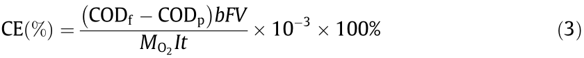
A series of experiments were conducted to investigate the removal of 2,4-DCP at a current density of 5 to 30 mA·cm-2 and a flow rate of 15 to 120 mL·min-1 . As shown in Fig. 3(a), increasing the current density from 5 to 30 mA·cm-2 increased 2,4-DCP removal from 5%–28% to 18%–71% in AC mode. Because the limiting current density (0.6 mA·cm-2 ) for the anodic oxidation of 10 mg·L-1 2,4-DCP was considerably lower than the applied current density, 2,4-DCP was degraded under diffusion-controlled conditions. Nevertheless, when the flow velocity was increased in the range 15–120 mL·min-1 , the mass transfer coefficient increased from 2.5 × 10⁶ to 2 × 10⁵ m·s-1 . The decrease in retention time from 160 to 20 s under continuous operation resulted in a 70.7%–78.5% decrease in 2,4-DCP removal under AC mode. Similar results were also reported by Wang et al. [32], who found enhanced electrochemical oxidation efficiency at lower flow rates and higher applied current densities. Similarly, for CA mode, 2,4- DCP removal increased from 30%–85% (5 mA·cm-2 ) to 81%–99%(30 mA·cm-2 ) with increasing current density and decreased from 85%–99% (15 mL·min-1 ) to 30%–81% (120 mL·min-1 ) with increasing flow rate. The rate constant obtained under CA mode was one order of magnitude greater than that under AC mode (Figs. 3(c) and (d)), indicating the inherent dependence of synergistic cathode/anode interactions on the flow direction. Fig. S2 in Appendix A compares 2,4-DCP removal under the two operational modes at 20 mA·cm-2 and 60 mL·min-1 . Under CA mode, almost complete removal of 2,4-DCP was achieved after 5 min of electrolysis, compared with only 16.8% removal under AC mode. Based on a flow rate of 60 mL·min-1 , raising the current density from 5 to 30 mA·cm-2 increased the rate constant from 0.19 to 0.21 min-1 in CA mode, which is approximately 11.2–78.1 times that in AC mode (Fig. 3(c)). When the current density was fixed at 20 mA·cm-2 , increasing the flow rate from 15 to 120 mL·min-1 enhanced the oxidation rate because of improved flow-through convective diffusion in the porous structure of the anode. This accounts for the increase in the rate constant from 0.13 to 0.28 min-1 in CA mode, which is approximately 6.7–11.2 times that in AC mode (Fig. 3(d)). The kinetic behavior of 2,4-DCP oxidation in CA mode appeared to be more sensitive to the flow rate, as indicated by the nearly one order of magnitude higher areanormalized apparent rate constant (0.036–0.079 m·s-1 ) compared to that for AC mode (Table S1 in Appendix A). This implies that ·OH-mediated oxidation was predominantly limited by mass transfer following cathodic activation (discussed below) when the wastewater stream flowed from the cathode to the anode.
《Fig. 3》
Fig. 3. 2,4-DCP removal performance of the TCE reactor as a function of flow direction, current density, and flow rate. Removal efficiency in (a) AC and (b) CA modes as a function of current density and flow rate. Removal kinetics as a function of (c) current density at a flow rate of 60 mL·min-1 and (d) flow rate at a current density of 20 mA·cm-2 for both flow modes (Kobs is the observed rate constant). (e) COD removal and (f) current efficiency in AC mode (hollow symbols) and CA mode (solid symbols) as a function of current density and flow rate (AC: waterstream from anode to cathode; CA: waterstream from cathode to anode). Influent solution ([2,4-DCP] = 10 mg·L-1 , [NaClO4] = 100 mmol·L-1 ) was electrolyzed.
In addition, water electrolysis resulted in the release of H+ near the anode and OH– near the cathode, and the difference between CA and AC modes was also associated with differences in the migration of H+ or OH–, particularly at high current densities. In CA mode, OH– produced from the cathodic hydrogen evolution reaction (HER) diffused to the anode, resulting in a slight increase in the pH value near the anode due to neutralization of protons produced from water oxidation (Fig. S3 in Appendix A). In this case, deprotonated 2,4-DCP (pKa = 7.8) was more likely to be adsorbed on the anode via electrostatic interactions, which facilitated the subsequent anodic oxidation. As shown in Fig. S4 in Appendix A, the CV curve exhibited a minimum potential of 1.66 V vs SHE for 2,4-DCP oxidation, and the intensity of the oxidative peaks was sensitive and positively related to the pH value. This indicates that 2,4-DCP oxidation is more favorable under higher pH conditions. Similarly, the typical oxidative intermediates, such as 2-CP and 4-CP, had pKa values of 8 to 9 [33], making them more reactive at higher pH values. Together, these factors allowed the TCE reactor to degrade 2,4-DCP with a maximum overall COD removal of 72.5% (Fig. 3(e)) and a current efficiency of 35.5% (Fig. 3(f)) under CA operation, which are considerably higher than the values under AC operation.
《3.4. Mechanistic insight into the impact of hydraulic flow》
3.4. Mechanistic insight into the impact of hydraulic flow
To further elucidate the 2,4-DCP degradation mechanism of the TiSO-based TCE reactor, the intermediate products were analyzed using UPLC–quadrupole–time-of-flight (UPLC–Q–TOF) mass spectrometry based on the mass-to-charge ratio (m/z). For AC mode, the results (Fig. S5 in Appendix A) matched those reported in previous studies, where six types of typical intermediates were detected during the electrochemical oxidation of 2,4-DCP [34,35]. In contrast, different intermediate products were detected for CA mode, indicating the reaction pathway and selectivity depend on the reaction sequence determined by the flow direction. Fig. S6 in Appendix A shows the accumulation of chlorinated dihydroxybenzenes (2 or 3) (m/z = 142.9342) and chlorinated benzoquinones (4 or 5) (m/z = 140.9376), which were characterized as the main intermediates in AC mode (Fig. 4). The reactions involve direct and indirect anodic oxidation of 2,4-DCP and direct cathodic reduction of chlorinated benzoquinone. In comparison, the characteristic intermediates observed for CA mode were phenol (m/z = 93.1581) and CPs (8 or 9) (m/z = 126.7408), whose relative abundance increased within the first 2 min, followed by a rapid decline without noticeable accumulation. Therefore, the cathodic reduction of 2,4-DCP and the anodic oxidation of phenol (10), hydroquinone (11), or catechol (12) are the most probable relevant reactions.
《Fig. 4》
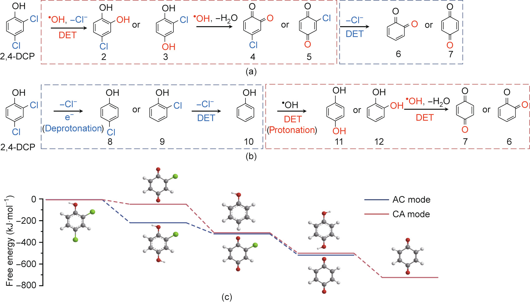
Fig. 4. Mechanism under (a) AC and (b) CA mode, and (c) DFT calculation for 2,4-DCP degradation at anode and cathode potentials of 2.38 and –1.45 V vs SHE, respectively.
The mechanistic insight into the impact of the flow mode can also be explained in the context of the difference in free energy for the two operational modes predicted by DFT calculations (Fig. 4). As shown in Fig. S7 in Appendix A, the activation energy for electro-reduction was lower than that for electro-oxidation. Specifically, the minimum potentials required for anodic oxidation of 2,4-DCP, phenol (10), hydroquinone (11), and catechol (12) were 1.90, 1.85, 1.40, and 1.50 V vs SHE, respectively, whereas the cathodic reduction of CPs (8 or 9), chlorinated benzoquinones (4 or 5) occurred at maximum potentials of –1.55, –1.55, –0.55, and –0.75 V vs SHE, respectively. Considering the similar redox nature of the DET of dihydroxybenzenes (11 or 12) and benzoquinones (6 or 7), the calculation of the overall free energy was simplified based on 1,4-benzoquinone (7). As revealed in Table S2 in Appendix A, the free energy was calculated to be –488.4 and –684.7 kJ·mol-1 for AC and CA modes, respectively, at anode and cathode potentials of 2.38 and –1.45 V vs SHE, respectively, indicating a more thermodynamically favorable pathway for 2,4-DCP degradation under CA mode. As shown in Fig. 4(c), the conversion of o-chloro-dihydroxybenzene (3) to o-chloro-p-benzoquinone (5) was the limiting step for AC mode, which could be alleviated by implementing cathodic reduction before anodic oxidation. Owing to the considerably lower energy required for the dechlorination of CPs (8 or 9) (–250.4 kJ·mol-1 ), cathodic reduction allows the more ther modynamically feasible dechlorination process to occur under a low applied cathode potential (E0 = –1.15 V vs SHE). The formation of phenol as a key intermediate increases the activity for subsequent anodic DET oxidation (Fig. S7) and ·OH attacks, which provides the most likely explanation for the high activity and high selectivity. Compared with that in AC mode, a high electric energy input is not required because cathodic reduction greatly decreases the minimum potential and activation energy (Umin in Eq. (7)) of 2,4-DCP, resulting in enhanced current efficiency and electrochemical mineralization (Fig. 3). Another advantage of CA operation is the lower biotoxicity of the dechlorinated intermediates (Fig. S8 in Appendix A). In this way, we were able to effectively destroy more CP pollutants with the removal efficiency more than 85% (Fig. S9 in Appendix A; 20 mA·cm-2 and 60 mL·min-1 ).
《3.5. Numbering-up strategy for scaling up the REM module》
3.5. Numbering-up strategy for scaling up the REM module
Based on the above results, we attempted to scale up the flowthrough electrolytic reactor based on the TCE configuration. In an electrochemical system, the area-to-volume ratio (A/V), that is, the specific electrode area (AS), is the key parameter that determines the inherent conversion capacity of the electrochemical system [36]. The importance of AS must be emphasized when the REM is scaled up to a larger size.
If the electrochemical system is scaled up along the axial length of the tubular reactor (PPE), the size and volume of the reactor will increase at the expense of a decline in AS:

where L is the axial length of the electrolytic cell, and r is the radius of the planar electrode. Although it is theoretically possible to scale up a PPE reactor by increasing the electrode area, this not only adds complexity to electrode fabrication and process integration but also causes nonuniformity in the primary current distribution on the electrode [37].
Because the TCE configuration allows water to flow through the side wall of the anode, the cylindrical geometry provides a higher surface-to-volume ratio than that of the planar geometry. Scaling up the electrolytic cell can be achieved simply by numbering up the TCE arrays, in which AS is independent of the axial length and volume of the reactor:

where r1 is the radius of the inner tube of a single TCE module, R is the radius of the reactor, and n is the number of TCE modules. This design enables modularization of TCE arrays with arbitrary axial lengths and numbers to create integrated electrolytic reactors that depend on the amount of wastewater to be treated in engineered applications.
To evaluate the effectiveness of the numbering-up strategy, we designed an electrochemical reactor containing TiSO TCE arrays with n = 1, 2, and 3 (Fig. 5(a)) and tested the overall performance of 2,4-DCP degradation (10 mg·L-1 ). Increasing the n value resulted in a higher removal efficiency, higher current efficiency, and lower energy consumption due to the increased area-to-volume ratio, particularly in AC mode, which offered slower kinetics. At the same current intensity (4 A), increasing n from 1 to 3 caused the removal efficiency to increase from 27.3% to 51.6% in AC mode and from 92.5% to 99.4% in CA mode (Fig. 5(b)) and the energy consumption per order (EEO) to decrease from 24.6 to 10.8 kW·h·m-3 in AC mode and from 3.0 to 1.5 kW·h·m-3 in CA mode (Fig. 5(c)). Moreover, the feasibility of the numbering-up strategy for scale-up was confirmed by the stable 2,4-DCP removal efficiency (Fig. S10 in Appendix A). Despite the similar cell voltages (4.7, 3.8, and 3.5 V for n = 1, 2, and 3, respectively) for the two modes, the energy consumption in CA mode was nearly one order of magnitude greater than that in AC mode because the decisive factor was effluent residual concentration (Cp; Eq. (2)) rather than the removal efficiency. The considerably higher energy consumption could be interpreted in the context of a higher Cp due to less efficient destruction of organic pollutants in AC mode. This corresponds to the lower current efficiency and COD removal in AC mode (68.7%–87.0% and 64.2%– 87.9% lower, respectively) than those in CA mode (Fig. S11 in Appendix A). The lowest EEO obtained at 1.5 kW·h·m-3 (99.4% removal) is in the range of values for the advanced electrochemical oxidation process of the membrane electrode on a laboratory scale (< 2.0 kW·h·m-3 ) [20]. Compared with conventional electrochemical treatment (summarized in Table S3 in Appendix A), a higher energy consumption (several orders of kilowatt-hours per cubic meter) (Table S3 [37,38]) was the consequence of the higher thermodynamic potential necessary for ·OH production (2.38 V vs SHE) and side parasitic reactions, such as oxygen evolution by water electrolysis. Despite this, the TCE-based modularized process is still competitive for larger-scale decentralized treatment of highsalinity industrial wastewater.
《Fig. 5》
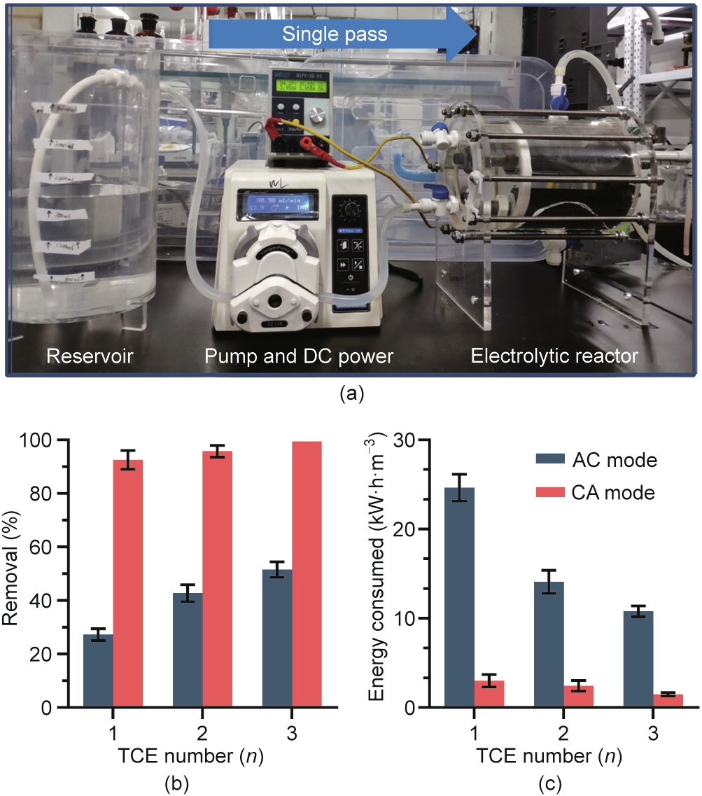
Fig. 5. (a) Optical images of the modularized TCE electrolytic reactor (n = 1, 2, 3); (b) removal efficiency of 2,4-DCP and (c) energy consumption per order under AC and CA modes. Tests were performed at [2,4-DCP] of 10 mg·L-1 , total current of 4 A, and flow rate of 60 mL·min-1 .
《4. Conclusions》
4. Conclusions
Based on the above results, the following conclusions can be drawn. The TCE configuration with a titanium suboxide ceramic anode and stainless-steel cathode was shown to be suitable for scale-up of the reactor. In the TCE configuration, the electrode surface is orthogonal to electric field lines everywhere, and the ohmic resistance is inversely proportional to the length of the electrode. The TCE configuration can be operated in either AC or CA mode based on the flow direction, creating adjustable conditions for selective degradation of pollutants. In CA mode, 98% removal of 2,4-DCP and 72.5% removal of COD were achieved because the kinetic constant was one order of magnitude higher than that in AC mode under flow-through single-pass operation. The TCE configuration was also shown to be suitable for a numbering-up strategy to scale up the electrochemical reactor without increasing the ohmic resistance or reducing the specific electrode area, which achieved 99.4% removal of 2,4-DCP with an energy consumption of 1.5 kW·h·m-3 when three TCE modules were employed. This study provides a reasonable, easy-to-handle, and reliable strategy for scaling up REM reactors, which can also be extended to realize the removal of other recalcitrant organic pollutants and decentralized electrochemical wastewater treatment.
《Acknowledgments》
Acknowledgments
This work was supported by the National Natural Science Foundation of China (U21A20161 and 51822806), State Key Laboratory of Urban Water Resource and Environment, China (Harbin Institute of Technology) (2020DX07), and Heilongjiang Touyan Innovation Team Program, China (HIT-SE-01).
《Compliance with ethics guidelines》
Compliance with ethics guidelines
Shuzhao Pei, Yi Wang, Shijie You, Zhanguo Li, and Nanqi Ren declare that they have no conflict of interest or financial conflicts to disclose.
《Appendix A. Supplementary data》
Appendix A. Supplementary data
Supplementary data to this article can be found online at https://doi.org/10.1016/j.eng.2021.11.017.


 京公网安备 11010502051620号


