
《1. Introduction》
1. Introduction
Aerogels are typical three-dimensional (3D) porous materials that have attracted a great deal of attention due to their excellent properties and broad applications [1,2]. In recent years, 3D fibrous aerogels made from fibers with extraordinary properties have drawn a tremendous amount of attention due to their superior characteristics, which include interconnected networks, low density, high porosity, high surface area, and low thermal conductivity [3–6]. Therefore, such 3D fibrous aerogels, which are also known as ‘‘sponges,” are ideal candidates for applications in the field of thermal insulation [7,8], solvent absorption [9], oil absorption/separation [10–12], cell culture [13], stimuli-responsive devices [14,15], electromagnetic shielding [16,17], water remediation [18], and particle filters [19,20]. In particular, among the various 3D electrospun polymeric aerogels that have been reported in the literature, electrospun polyimide fibrous aerogels (PIFAs) have attracted considerable attention due to their thermal insulation, high porosity, and excellent mechanical properties [8,21–23].
Polyimide (PI)-based aerogels can be fabricated using either freeze-drying (FD) or supercritical drying (SD) methods [8,24– 27]. FD and SD techniques can effectively restrain the collapse of the pore structure during drying [28–32]. However, both techniques require sophisticated instruments to create either ultralow temperatures under vacuum conditions or high temperatures in ultrahigh-pressure environments. In addition, their timeconsuming, costly, low-producing, and scale-restricted drying processes are fatal flaws that hinder further practical applications of FD and SD techniques, especially for large-scale production. Convenient and inexpensive large-scale preparation is crucial for practical applications to be possible for such techniques. Compared with traditional drying methods, vacuum-drying (VD), which does not require special facilities, is both time-saving and convenient. In the literature, the VD technique has been applied to prepare several polymer-based aerogels. A bridged silsesquioxane aerogel prepared by VD showed a compressive modulus of 139.2 kPa with a density of 85 mg·cm–3 at 60% strain [33]. Yet only 20 cycles of the loading–unloading process were conducted at 30% strain, and too much alcohol was consumed during the drying process of this organic silicon aerogel. Li et al. [34] reported a reduced graphene oxide (GO) aerogel prepared by a VD/ambient drying method, which exhibited a compressive stress of 0.019 MPa and a density of 5.3 mg·cm–3 . However, the graphene aerogel reported in that work had an energy-loss coefficient greater than 50% and a degradation of compressive strength of over 20% after only 10 cycles of compressive work. These weak mechanical properties probably originate from the rather low concentration and disorder of the GO lamella in the precursor dispersion. A phenolic polymerderived carbon aerogel for use in organic solvents absorption was prepared through VD, and exhibited a low density of 25 mg·cm–3 [35]. Nonetheless, the method introduced in that work is only appropriate for producing phenolic polymer-derived carbon aerogels, rather than neat polymer aerogels. Plus, the health issues that have been reported with the use of ZnCl2 limits its application. PI aerogels made using VD after a sol–gel and solvothermal imidization process have been reported [36,37]. However, these kinds of PI aerogels show relatively weak mechanical properties at relatively high densities. For example, using aromatic dianhydrides and triamines as monomers, PI aerogels prepared by means of the sol– gel followed by hydrothermal imidization process and then VD, exhibited a density greater than 140 mg·cm–3 but a maximum stress of 95% and 87% after only 10 cycles of the loading–unloading process. The relatively poor fatigue resistance and structural stability of these PI aerogels mainly resulted from the low molecular weight of the poly(amic acid) (PAA) used in that work, in comparison with the PAA synthesized from dianhydrides and diamines. Furthermore, a solvothermal imidization process that is maintained for over 10 h is harmful to the structural stability of the PAA precursor gels in an atmosphere with high temperature and pressure. Therefore, a novel energy-, time-, and cost-saving method is greatly required for the preparation of highperformance PIFAs.
In this research, we highlight a strategy involving freezeextraction followed by VD to fabricate PIFAs using short PI fibers as a skeleton. Strengthening the initial framework stiffness of the precursor aerogel and reducing the capillary pressure caused by solvent evaporation resulted in no obvious volume shrinkage or structural cracking being observed during the entire VD process. The obtained vacuum-dried aerogels exhibited excellent mechanical performance, superior thermal insulation, and low thermal conductivity. Further modification by polysilazane significantly enhanced the thermal properties and fire retardancy of the composite aerogels.
《2. Experimental section》
2. Experimental section
《2.1. Materials》
2.1. Materials
Electrospun short PI fibers from monomers of pyromellitic dianhydride (PMDA) and 4,4' -oxidianiline (ODA) with an average length of 1 mm were provided by Jiangxi Xiancai Nanofibers Technology Co., Ltd., China. ODA (Changzhou Sunlight Pharmaceutical Co.) and 3,3' ,4,4' -biphenyltetracarboxylic dianhydride (BPDA; Changzhou Sunlight Pharmaceutical Co.) were purified by sublimation before use. N,N-dimethylacetamide (DMAc; 99%; Shanghai Chemical Reagents Co., China) was purified by distillation before use. Triethylamine (TEA; 99%; Tianjin Zhiyuan Chemicals Co., Ltd., China), formic acid (88%; Tianjin Zhiyuan Chemicals Co., Ltd., China), tetrahydrofuran (THF; 99%; Tianjin Zhiyuan Chemicals Co., Ltd.), and polysilazane (Anhui Lota Silicon Oil Co., Ltd., China) were used as received without further purification.
《2.2. Preparation of PAA》
2.2. Preparation of PAA
In brief, equal molar ratios of BPDA and ODA were reacted in DMAc at 0 °C for 24 h, followed by a partial amination process with a 60% molar ratio to BPDA of TEA. After stirring for 0.5 h, the obtained solution (6.2 wt%) was stored in the refrigerator for future use.
《2.3. Preparation of PIFAs》
2.3. Preparation of PIFAs
In a typical experiment, 1.02 g of short PI fibers (1 mm) were mixed with 16.45 g of diluted partially aminated PAA solution with 35.57 g of DMAc and 0.71 g of deionized water (2 wt% weight ratio to DMAc). The prepared dispersion was transferred into an aluminum foil pan and frozen in liquid nitrogen until the dispersion transformed into a solid, which was then slowly immersed in a non-solvent (water/ethanol/formic acid, 70:30:10, v/v/v) with stirring (500 r·min–1 ) to accelerate the solvent-extraction process. The whole solvent-extraction process took approximately 3 h for a sample with a thickness of 1.8–2.2 cm and 1.5 h for a sample with a thickness of 0.8–1.2 cm. When the freeze-extraction process was complete, the porous and rigid wet aerogel was washed with ethanol, followed by VD at 120 °C for 2 h. After the VD process, the precursor aerogel was heated to 300 °C (2 °C·min–1 ) and annealed for 1 h under a nitrogen atmosphere to implement the imidization process. Depending on the solid contents of the PAA solutions, the as-prepared PIFAs were denoted as PIFA-1.4, PIFA-1.6, PIFA1.8, and PIFA-2.0, with densities of 39.1, 42.4, 46.7, and 52.8 mg·cm–3 , respectively. The mass of the aerogels was measured using an analytical balance; the volume was determined by the length, width, and height of the rectangular samples; and the density (mass/volume) of the aerogels was then obtained.
《2.4. Preparation of polysilazane-modified PIFAs》
2.4. Preparation of polysilazane-modified PIFAs
The PIFAs were immersed in a polysilazane tetrahydrofuran solution (2 wt%) and squeezed to facilitate the absorption process. This was followed by air drying at 80 °C to obtain polysilazanemodified PI fibrous aerogels (PszmPIFAs). The PszmPIFAs were further heated at 180 °C for 2 h and at 430 °C under a nitrogen atmosphere for 1 h to cure the polysilazane. The PIFAs that were modified following this protocol once, twice, and three times were denoted as PszmPIFAs1, PszmPIFAs2, and PszmPIFAs3, respectively.
《2.5. Characterization》
2.5. Characterization
A scanning electron microscope (SEM; VEGA 3 SBU; TESCAN, Czech Republic) was used to observe the morphologies of the PI fibers and the aerogel samples. Compression tests and cyclic compression tests were performed on a compression tester (CMT8202; SANS, China) at a compression rate of 50 mm·min–1 . Tests with 20 000 compression cycles were conducted, and the plots for the 1st, 20th, 200th, 2000th, and 20 000th cycles were recorded. Transmission electron microscopy (TEM; Titan G2 60-300; FEI, USA) was used to observe the morphologies of the PszmPIFAs. Thermogravimetric analysis (TGA) was performed on a TGA-55 (TA Instruments, USA) under a nitrogen atmosphere with a heating rate of 10 °C·min–1 from 50 to 800 °C. Thermal conductivity was measured using a Hot Disk thermal constants analyzer (TPS 2500S; Hot Disk, Sweden) with a Kapton sensor (5465; Hot Disk). The density of the aerogels was calculated by (1 – ρ0/ρbulk) × 100%, where ρ0 the apparent density of the aerogel and ρbulk = 1.4 g·cm–3 is the density of PI in the bulk state. A Quantachrome Autosorb IQ2 automatic adsorption/desorption analyzer (USA) was used to measure specific surface areas, as well as the pore size and distribution of the aerogel materials.
《3. Results and discussion》
3. Results and discussion
《3.1. Fabrication of PIFAs and PszmPIFAs》
3.1. Fabrication of PIFAs and PszmPIFAs
The concept for the preparation of the PIFAs and PszmPIFAs is schematically shown in Fig. 1. In general, short PI fibers can be obtained by continuous electrospinning, thermal imidization, and pulverizing. However, the short PI fibers that are obtained by pulverizing PI nonwovens possess uneven fiber length and aspect ratios, which affect the pore structures and mechanical performance of the resultant PIFAs. In this work, the short fibers were provided by Jiangxi Xiancai Nanofibers Technology Co., Ltd., China. As shown in Fig. S1 in Appendix A, the short PI fibers possessed a homogeneous size, with an average length of about 1 mm and diameter of about 1.2 μm. These short PI fibers were then mixed with PAA to form a homogenous, viscous, and stable suspension, in which the PI fibers could be dispersed well and bonded by PAA via a ‘‘self-gluing” mechanism [8,23]. To be precise, because the PAA can be thermally imidized further, the additional PAA acted as a glue on the short PI fibers, which were then converted into PI, and finally formed a composite structure with the PI resin self-gluing the short PI fibers. It was notable that the minor addition of water as a solvent increased the surface tension of the solvent, thereby restraining the volume shrinkage upon freezing [3].
《Fig. 1》
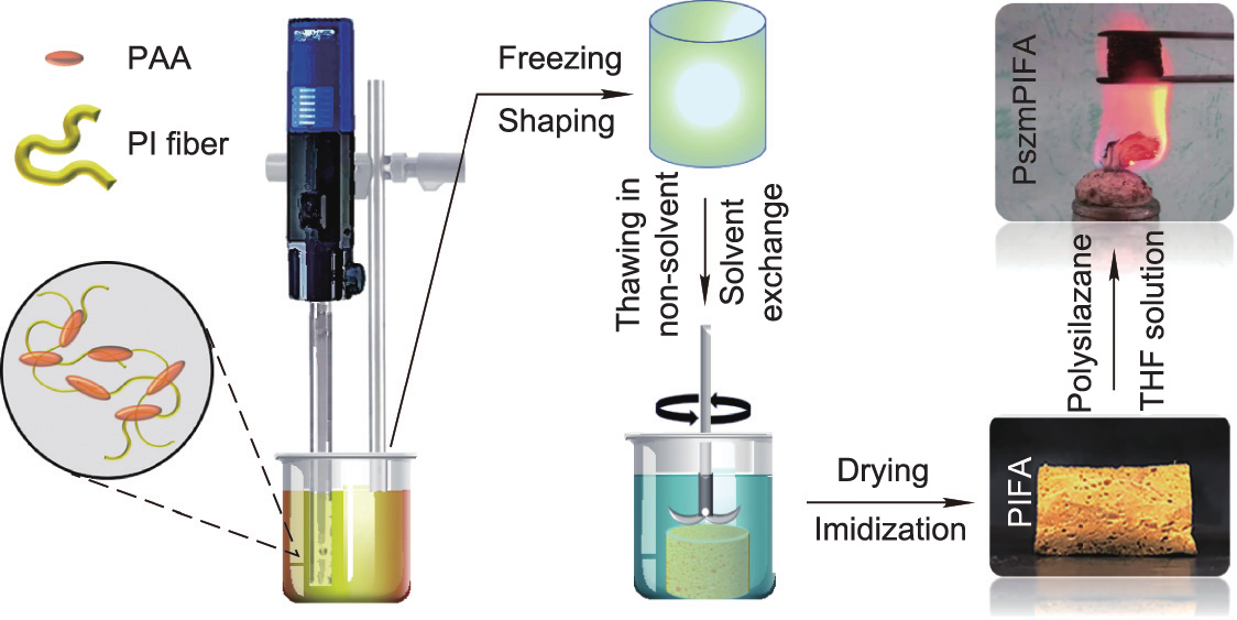
Fig. 1. Structural design and process used to make PIFA and PszmPIFA.
It is also notable that special drying methods were not required in this case because a cellular structure had already formed after the non-solvent phase separation induced by the non-solvent exchange. In this method, large pores formed in the outer parts of the aerogels due to the expansion of ice and solvent exchange. The formation of a porous structure before drying facilitated the elimination of polar solvents [34,38,39]. Moreover, the robust precursors of the PIFAs were able to withstand the capillary forces originating from the polar solvents, which allowed the drying process to be conducted in an ordinary vacuum oven while maintaining the porous structure [35,38–41].
In general, the freeze-extraction/VD preparation process used in this work saves energy, time, and costs. First, the raw PI fibers used in this work were commercially provided by Jiangxi Xiancai Nanofibers Technology Co., Ltd., China, and were thus much cheaper than lab-made PI fibers. In addition, the devices used in this work are much cheaper than specialized machines such as freeze-driers and supercritical driers. In order to prepare samples with the same size, such as 0.09 m2 , traditional FD and SD processes require a freeze drier (850 W, LC-10 N-50B; Shanghai Lichen Bangxi Instrument Technology Co., Ltd., China) or a supercritical drier (12 kW, SFE-02; Nantong Yichuang Experimental Instrument Co., Ltd., China) to be operating for at least 48 h. In contrast, the VD process used in this work only requires a normal vacuum oven (300 W, DZF-6020A; Shanghai Lichen Bangxi Instrument Technology Co., Ltd.) operating for around 10 h, which saves both energy and time in comparison with the other two techniques.
《3.2. The hierarchical cellular structure of PIFAs》
3.2. The hierarchical cellular structure of PIFAs
It was observed that the higher solid content of the PAA was, the more visible was the honeycomb structure of the aerogels from PIFA-1.4 to PIFA-2.0 because continuous porous solid phases were more likely to form as the solid content of the PAA increased (Figs. 2 (a–d)). Cross-sectional SEM images of PIFA-2.0 are shown in Figs. 2 (d–f). This aerogel exhibited a dual pore structure with major pores (i.e., pores formed by non-solvent-induced phase separation during the freeze-extraction process) and minor pores (i.e., pores between the fibers). The aerogel exhibited an open-cellular architecture with interconnected pores through triangular junctions and a major cellular pore size of 70–80 μm. The fibrous cell walls consisted of minor pores constructed by overlaid short PI fibers. Simultaneously, PI aggregated on the short fibers and acted as a glue, reinforcing the mechanical properties of the aerogel [42].
《Fig. 2》

Fig. 2. Microstructures and structural formability of PIFAs. (a–c) SEM cross-sectional images of PIFA-1.4, PIFA-1.6, and PIFA-1.8; (d–f) SEM cross-sectional images of PIFA-2.0 under different magnifications; (g) shrinkage rates and density of PIFAs; (h) porosity of PIFAs.
It is well known that thermal treatment induces significant volume shrinkage in PI aerogels due to thermal shock stress during thermal treatment. Nevertheless, with an increase in the mass ratio of fibers to PAA, the PIFA shrinkage decreased from 29.5% to 19.2%, indicating that the structural stability of the PIFAs clearly improved. The shrinkage of the PIFAs prepared by the freezeextraction method was comparable to or even better than that of PIFAs prepared using FD, and lower than the shrinkage of PIFAs prepared using the SD method [43–46]. With an increase in the amount of PAA, an escalating trend was observed in the apparent density of the PIFAs, ranging from 39.1 mg·cm–3 (PIFA-1.4) to 52.8 mg·cm–3 (PIFA-2.0) (Fig. 2(g)). Although shrinkage occurred during the thermal imidization process, the porosities of the PIFAs were greater than 96.0% (96.2%–97.2%) (Fig. 2(h)).
As shown in Fig. 3(a), the obtained specific surface areas of the PIFAs were in the range of 2–4 mL·g–1 , which coincides with the values for other porous materials [9,23]. Fig. 3(b) demonstrates the existence of a bimodal porous structure in the PIFAs. The pore sizes were mainly distributed within the ranges of 3–27 and 60– 80 μm, respectively. The small pores were derived from the spaces between the entangled fibers, while the big pores resulted from the non-solvent-induced phase separation during the freezeextraction process. The porous characteristics shown in Fig. 3 agree well with the SEM results shown in Fig. 2.
《Fig. 3》

Fig. 3. (a) Nitrogen adsorption–desorption isotherm; and (b) pore size distributions of the PIFAs. STP: standard atmospheric pressure; dV(d): pore diameters.
《3.3. Mechanical properties of PIFAs》
3.3. Mechanical properties of PIFAs
The compressive properties of the PIFAs are shown in Fig. 4. It was found that the maximum stress of the PIFAs gradually increased from 49 to 189 kPa as the loading amount of PAA increased (Fig. 4(a)). Due to the good compression resistance, the resulting PIFAs could withstand a weight of 200 g (581 times greater than the weight of the PIFAs themselves) without obvious deformation and a weight of 2 kg without any fracture (see insets of Fig. 4(a)). The stress–strain (σ–ε) curves for PIFA-2.0 at various maximum compression strains of 20%, 30%, 40%, 50%, and 60%, with the stress ranging from 12 to 211 kPa, are presented in Fig. 4(b). It should be noted that, in applications, a monolithic PI aerogel requires an outstanding compressive fatigue resistance. Therefore, the compressive fatigue durability of the PIFAs (taking PIFA-2.0 as an example) was evaluated by conducting a compression cycling test of at least 20 000 loading–unloading cycles at a compression strain of 50% (Fig. 4(c)). Remarkably, PIFA-2.0 maintained 94% of its initial height, demonstrating only a negligible plastic deformation of 6.33% at 50% compression, even after 20 000 cycles, thus further highlighting the excellent fatigue resistance of the PIFAs (Fig. 4(d)). Although the maximum stress of PIFA-2.0 decreased from 189 to 125 kPa during the whole compressive test, the PIFA still retained over 66% of its initial strength, thereby demonstrating its durable cycling performance and structural stability. The variation of the Young’s modulus, which decreased from 378 to 250 kPa, was the same as that of the compressive strength. We estimated the work performed in the compression (U) and the energy dissipation ( ), which could be determined from the hysteresis loops between the loading and unloading curves, yielding energy-loss coefficients (
 (Fig. 4(e)). The energy-loss coefficient of PIFA-2.0 decreased from 0.27 for the first cycle to 0.26 for the 2500th cycle, and then remained at 0.24 for subsequent cycles (Fig. 4(e)). The energy-loss coefficient of the PIFAs in this work is smaller than those reported for other aerogels [7,47–49].
《Fig. 4》

Fig. 4. The multicycle compressive properties of PIFAs. (a) Stress–strain plots of PIFAs for the first cycle; (b) stress–strain plots during loading–unloading processes with different levels of compression strains; (c) stress–strain plots for different compression cycles at a compressive strain of 50%; (d) relative height evolution and maximum stress after different compression cycles; (e) Young’s modulus and energy-loss coefficient as functions of compressive cycles; (f) sketch of the bending of fibrous cell walls under compression. F: the force imposed on the pore structures; a: the pore structure containing a high aspect ratio and rough PI fibers; b: the pore structure containing mere small aspect ratio PI fiber.
It is common for fibers with high aspect ratios (length/diameter) to possess a great deal of contact and to entangle and twist with each other, increasing the interactions among them [50]. The PI fibers used in this work had a length of about 1 mm and a diameter of about 1.2 μm, with a large aspect ratio of 833, so they possessed the flexibility to entangle and twist with each other. Such a high aspect ratio resulted in much better fatigue resistance than the PIFAs reported in our previous work [8,23]. As illustrated in Fig. 4(f), the cell walls fabricated by PI fibers with a small aspect ratio are discontinuous, fragile, and flexible, with a tendency to collapse and insufficient ability to recover, caused by bending-dominated buckling. In contrast, in a honeycomb structure, the cell walls fabricated by well-bonded and highly tangled PI fibers with a high aspect ratio possess a more robust and continuous structural support, which is beneficial for transferring the loading stress along the fibers—an essential part of elastic recovery. Furthermore, rough PI fibers serve as strong pillars and beams in the cell walls when such fibers are added, further strengthening the resilience of the honeycomb structure [7,13]. Using this method, lightweight PIFAs, which are 3D polyimide materials, can easily be prepared and possess both elasticity and excellent fatigue resistance, compared with the values reported in the literature so far (Table S1 in Appendix A).
《3.4. Thermal insulation performance of PIFAs》
3.4. Thermal insulation performance of PIFAs
Aerogels are most commonly used thermal insulation materials due to their low thermal conductivity, which stems from their high porosity. Because of their low solid fraction and high porosity, PIFAs prepared by the solvent-extraction method exhibit low thermal conductivity. Created by interconnected networks, tortuous porous paths result in low solid thermal transportation. Furthermore, the intertwined networks decrease the gas thermal conductivity of PIFAs by extending the flow space of air molecules. As shown in Fig. 5(a), as the density of PIFAs decreased, the thermal conductivity ( ) slightly decreased. Notably, the thermal conductivity of PIFA-1.4, PIFA-1.6, PIFA-1.8, and PIFA-2.0 was 40.4, 42.2, 42.8, and 44.0 mW·m–1 ·K–1 , respectively. As shown in Fig. 5(b), PIFAs (taking PIFA-2.0 as an example) exhibited a low conductivity (44.0 mW·m–1 ·K–1 ), which is comparable with those of other reported aerogels and sponges, including PI/rGO/Co aerogel [51], polybenzazole aerogel [47], PI fiber assembled sponge prepared by FD [8], SiO2–Al2O3 composite ceramic sponge [49], silver nanowires/PI sponge [52], and bamboo fiber-modified foam [53]. Furthermore, the PIFAs outperformed wood aerogels [48] in terms of low conductivity. It can be seen from Fig. 5(b) that the PIFAs in this work possessed both a low energy-loss coefficient at a large compressive strain and low thermal conductivity. These performances are promising for practical thermal insulation applications. We further observed the dynamic temperature distribution of PIFA-2.0 by means of infrared camera by heating the PIFA on a 350 °C platform for 30 min. As shown in Fig. 5(c), it was observed that a gradient temperature was distributed from the interface between the platform and the bottom of the sample through to the top of the sample. The temperature of the top surface of PIFA-2.0 (22 mm thick) remained at about 55.0 °C for 1 min; it then increased to 65.0 °C after 10 min of heating and subsequently remained near 75.0 °C after 20 min. After being removed from the 350.0 °C platform for 5 s, the temperature at the bottom and top surfaces dropped to 221.2 and 45.7 °C, respectively, which made it possible to pick up the PIFA from the top with a bare hand (Fig. 5(d)). These results demonstrate the PIFA’s excellent performance as a thermal insulator against a high temperature over a long period of time.
《Fig. 5》

Fig. 5. Thermal insulation properties of the PIFAs. (a) Thermal conductivity of the PIFAs; (b) thermal conductivity and energy-loss efficient of PIFA-2.0, as compared with those of aerogel-like materials reported in the literature; (c) infrared images of PIFAs on a 350 °C heating platform for 30 min; (d) a hand holding the PIFA after it had been heated on a 350 °C platform.
《3.5. Polysilazane-modified PIFAs》
3.5. Polysilazane-modified PIFAs
PI aerogels have great potential for use as lightweight fireretardant materials. Adding inorganic fillers can be an effective strategy to improve their fire resistance [54,55]. However, the addition of such fillers also results in the sacrifice of mechanical flexibility and a significant increase in density. Therefore, it would be better to modify PI aerogels with inorganic polymer materials, which possess more tenacity than inorganic particles. Herein, we developed a facile method to modify PIFAs through the adsorption of polysilazane solution followed by air drying. Polysilazane, a Si– N-containing inorganic polymer with high polarity, possesses good adhesion to different surfaces [56]. Therefore, it can easily form a coating on PI nanofibers (PINFs). After further thermal treatment at a high temperature, the polysilazane coating can be selfcrosslinked into a more stable compound to bind the PINFs [57].
As displayed in Fig. 6(a), the PI fibers of the PIFAs were wrapped and adhered by a layer of polysilazane. An ultrathin layer of polysilazane with a thickness of 42 nm was coated onto the PI fibers, as shown in the selected-area TEM image, serving as a glue to bind the PI fibers together (Fig. 6(b)). According to energy dispersive spectrometer (EDS) mapping of the cross-section, the PszmPIFA2 contained elements of carbon (C), nitrogen (N), oxygen (O), and silicon (Si), with the Si element deriving from the polysilazane and all elements being homogeneously distributed (Figs. 6(c–h)).
《Fig. 6》

Fig. 6. Representative graphs of PszmPIFAs. (a) SEM image of the cell wall of PszmPIFA2; (b) schematic and TEM images of the selected region at the edge of a PszmPIFA; (c–h) TEM and energy dispersive spectrometer (EDS) mapping spectrum images of the selected region at the edge of a PszmPIFA. K: the K shell of atom.
《3.6. Thermal and mechanical behavior of PszmPIFAs》
3.6. Thermal and mechanical behavior of PszmPIFAs
The thermal properties of the PIFAs and PszmPIFAs were investigated by means of TGA (Fig. 7(a)). All the samples were found to be thermally stable until 300 °C. The PIFAs started to decompose at around 350 °C, with weight loss that can be attributed to the release of CO2 and H2O to form residual carbon. In comparison, the PszmPIFA samples started to decompose at around 450 °C, with weight loss coming from the decomposition of PIFA to form residual carbon and the decomposition of polysilazane to form SiN4 [58]. The PszmPIFAs exhibited a decomposition temperature 100 °C higher than that of the PIFAs. PszmPIFAs that had been modified with polysilazane once, twice, and three times had residues of 68.2%, 76.1%, and 78.5%, respectively, which were much higher than that of PIFAs (60.4%). Fig. 7(b) presents the weight loss of PI-based aerogels versus their burning time curves. During the combustion process, PszmPIFA1, PszmPIFA2, and PszmPIFA3 preserved 66.9%, 73.9%, and 77.5% of their original weight, respectively, when exposed to a high-temperature flame for 60 s. These values were clearly higher than that of PIFA-2.0, revealing that the PszmPIFAs possessed much better flame retardancy than the PIFAs, probably due to the coating of polysilazane. The polysilazane coating forms a gas barrier around the PIFAs to separate the sample from oxygen, and thus prevents the generation of fire. In addition, during the burning, the polysilazane thermally decomposes into inorganic Si–O–Si bonds under an oxygen atmosphere [59], which further protects the PIFAs from burning and enhances the flame retardancy of the PszmPIFAs.
To our surprise, polysilazane not only improved the combustion behavior, but also decreased the thermal conductivity of the PIFAs. Compared with PIFA-2.0, a lower conductivity of 38.5 mW·m–1 ·K–1 was achieved from sample PszmPIFA1 (Fig. 7(c)). With an increased loading of polysilazane, the conductivity of PszmPIFA2 further decreased to 36.4 mW·m–1 ·K–1 . More intuitively, the dynamic temperature distribution of PszmPIFA2 was observed using the same method as that used for PIFA-2.0 (Fig. 7(d)). It was observed that the temperature of the top surface of PszmPIFA2 slowly increased from 45.9 to 68.8 °C in 30 min; furthermore, PszmPIFA2 maintained lower temperatures than those of PIFA2.0 during the whole high-temperature heating process, indicating that modification with polysilazane effectively reduced the thermal conductivity of the PIFAs.
《Fig. 7》
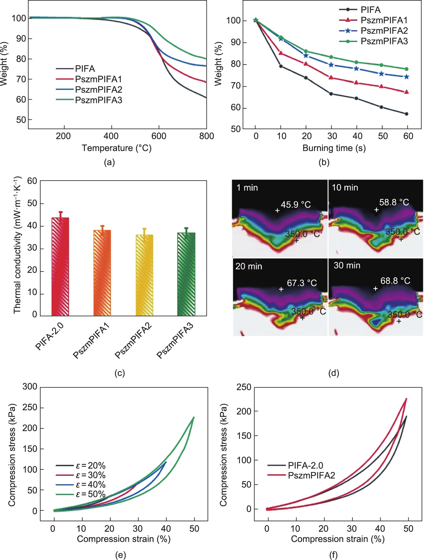
Fig. 7. Thermal insulation properties and mechanical performance of PszmPIFAs. (a) TGA curves of PI-based aerogels; (b) weight loss versus burning time for PI-based aerogels held over the flame of an alcohol lamp; (c) thermal conductivity of PI-based aerogels; (d) infrared camera images of PszmPIFA2 on a 350.0 °C heating platform for 30 min; (e) stress–strain plots of PszmPIFA2 during loading–unloading processes with gradient ascent strain; (f) stress–strain plots of PIFA-2.0 and PszmPIFA2 for the first compressive cycle.
Fig. 7(e) presents the stress–strain curves of a PszmPIFA (taking PszmPIFA2 as an example) at a maximum compression strain of 20%, 30%, 40%, and 50%. As can be seen, the maximum stress of PszmPIFA2 ranged from 36 to 224 kPa with an increase in strain amplitude. Furthermore, the compressive stress of PszmPIFA2 at 50% reached 224 kPa, which was 18.5% higher than that of PIFA2.0 (Fig. 7(f)). Thus, enhanced mechanical performance was induced by polysilazane modification, as the polysilazane wrapped around the junctions in the PI-based aerogels.
《3.7. Combustion behavior of PI-based aerogels》
3.7. Combustion behavior of PI-based aerogels
Although PI is one of the most well-known thermostable polymer materials, it loses its mechanical properties within quite a short time when exposed to a rather high temperature in air. During the combustion experiments (Fig. 8(a)), no fume or fire was released from the PI-based aerogels (PIFAs and PszmPIFAs) when the ignition source was removed, which demonstrates their self-extinguishing behavior. As shown in Fig. 8(b), when PIFA-2.0 was exposed to the alcohol flame, it deformed within several seconds and suffered from a severe volume shrinkage of almost 40% during the combustion process. In comparison, PszmPIFA2 maintained its shape without visible shrinkage or deformation during 60 s of combustion (Fig. 8(c)).
The high-temperature resilience and retardancy of PszmPIFA2 were further investigated by in situ compression in the flame of an alcohol lamp (~700 °C). As demonstrated in Figs. 8(d) and (e), PszmPIFA2 exhibited good elastic resilience during for a total of compression cycles without structural collapse and ignition upon flame burning, in comparison with the PIFA-2.0, which suffered from severe collapse and shrinkage, and turned into a compact bulk. Further investigation by SEM indicated that the cellular structure of PszmPIFA2 remained, while the honeycomb structure of the PIFA-2.0 was compressed into a dense lamellar structure (see SEM images in Figs. 8(d) and (e)). These results demonstrate that PszmPIFAs can serve as lightweight and tough insulators that are fireproof and heatproof for potential applications such as the construction industry or insulation layers in the aerospace and aviation industries.
《Fig. 8》

Fig. 8. (a) The self-extinguishing behavior of PIFAs and PszmPIFAs; (b, c) volume variation of (b) PIFA-2.0 and (c) PszmPIFAs2 when exposed to the flame of an alcohol lamp for 60 s; (d, e) compression-recovery behavior of (d) PIFA-2.0 and (e) PszmPIFA2 in the flame of an alcohol lamp with their SEM images after pressing and releasing with burning.
《4. Conclusions》
4. Conclusions
In summary, a facile freeze-extraction method followed by VD was developed to successfully prepare PIFAs using short electrospun PI fibers as a supporting skeleton. The proposed technique is time-, energy-, and cost-saving, as it does not involve special drying methods, in comparison with the two traditional drying techniques, FD and SD. The precursors of the PIFAs were able to withstand the capillary pressure originating from the polar solvent, making drying possible under regular vacuum conditions. The PIFAs that were obtained after imidization exhibited low density (≤ 52.8 mg·cm–3 ) and high porosity (> 96%). The PIFAs also possessed excellent mechanical properties and thermal stability. Moreover, they exhibited a good thermal insulating performance due to their high porosity and interconnected networks. Modification by coating the PIFAs with polysilazane significantly improved their fire resistance. We believe that the freezing-extraction/VD strategy can be extended to other material systems. With this facile and low-cost method, PIFAs and their composites are promising candidates for practical applications, such as lightweight building, thermal insulating, and fireproof layers for the construction and aviation industries, and high-temperature reaction catalyst carriers. In addition, by modifying the freezing and solvent-extraction setups, such as by using a larger tank and stirrer or by using a reversible moving conveyor, the novel freezingextraction/VD technique proposed in this work could be successfully applied for the production of large samples.
《Acknowledgments》
Acknowledgments
This work was financially supported by the National Natural Science Foundation of China (21975111, 21774053, and 51903123), and Advanced Analysis and Testing Center of Nanjing Forestry University.
《Appendix A. Supplementary data》
Appendix A. Supplementary data
Supplementary data to this article can be found online at https://doi.org/10.1016/j.eng.2021.08.024.


 京公网安备 11010502051620号


