

《1. Introduction》
1. Introduction
Unmanned intelligent systems such as legged robots can perform a variety of tasks in complex environments. One advantage of legged robots is their capability for highly dynamic motion, including actions such as running and jumping. However, legged robots have size and weight limits and thus require highperformance actuators. Unlike typical industrial systems, which have high-rated power actuators and operate in fixed working environments, legged robots often operate in complex environments that require fast-motion responses [1–3]. Therefore, legged robots require high explosive power actuators to provide high peak speed or high peak torque at specific moments during their dynamic motion.
Hydraulic actuators have high power and are naturally robust against impulsive loads. For example, the Atlas robot developed by Boston Dynamics uses hydraulic actuators to achieve highly diverse and agile locomotion [4]. However, hydraulic systems are inefficient when operated at constant pressure. It is thus difficult to position the onboard supply, which makes legged robots rather large and heavy [5]. Hydraulic systems may also leak oil [6].
Electric motor actuators are more compact and have a more constant output torque profile compared with hydraulic actuators. Pseudo-direct-drive systems use a high-torque motor in combination with a low-reduction-ratio gearing system. The actuator’s output force can thus be controlled accurately via the motor current with high transparency [7]. For example, the Cheetah robot [8– 10] developed by Massachusetts Institute of Technology (MIT) uses a high-torque-density motor actuator with a large gap radius [7,11]. However, large actuators are unsuitable for use in legged robots with a relatively large number of degrees of freedom (DoFs), such as humanoid robots.
Many legged robots with a high number of DoFs, including ASIMO [12], ATRIAS [13], and ANYmal [5], have strict actuator size limitations. These robots use small high-speed motors with relatively high-ratio reducers to support the heavy robot trunks [12–14]. However, high-ratio reducers increase friction and introduce nonlinear elements into the actuator, which means that the force cannot be controlled directly using the motor current. The National Aeronautics and Space Administration (NASA) Valkyrie [15], Cassie [16], and DLR robots [17] use series elastic actuators (SEAs) or similar force sensors to implement accurate actuator force control. However, the elastic parts of an SEA or a force sensor cannot absorb the explosive impacts that occur during dynamic motion. These robots have poor dynamic motion performance because the high-ratio reducer required for the SEA, or the force sensor used for force control, increases friction and introduces nonlinear elements into the actuator.
Animal muscles can provide high instant power for a diverse range of agile movements [18]. The relationship among the force, length, and velocity properties of muscles contributes to providing the explosive power necessary for dynamic movements such as throwing, kicking, and jumping [19]. In addition, the pair of cruciate ligaments that is present in animal joints serves as a variable transmission [20]. Animals can maintain a relatively constant core temperature through a dynamic balance between endogenous heat-production and heat-dissipation to the surrounding environment during movement [21]. In summary, animal muscles produce explosive power, have a variable transmission, and dissipate heat.
The reduction ratio represents a tradeoff between torque and speed. Some researchers have thus designed actuators with continuously variable transmissions or infinitely variable transmissions for use in robots [22,23]. These designs involve complex transmission chains that are difficult to install on small actuators. Another type of actuator uses two motors to control the sun gear and the ring gear of a planetary reducer [24–26]. In this type of system, an optimal control method is required to regulate the coupled relationship between the two motors. To enhance actuator heatdissipation, some robotic systems use liquid cooling systems to ensure that the actuator operation remains sufficiently stable to allow it to support dynamic motion [27–29]. However, liquid cooling systems require bulk liquid storage to perform the heatexchange operation and usually require integration of the liquid cooling channels into the robot system.
In this study, we propose an explosive electric actuator and its control method for application in legged robots. This actuator provides high peak speed or high peak torque at specific moments during robot dynamic motion. We perform jumping experiments using typical legged robots to verify the effectiveness of the proposed actuator. The main contributions of this work are summarized as follows:
(1) To eliminate the tradeoff between high speed and high torque for legged robots, we add a power allocation unit to control the rotational speed of the first-stage ring gear in a two-stage planetary gear train in order to adjust the reduction ratio. This highpower-density variable transmission allows continuous and efficient adjustment of the ratio of the speed to the output torque.
(2) The robot actuator cannot operate continuously in the highpower output state because of heat accumulation. Therefore, we design a heat-dissipating structure based on a composite phasechange material (PCM). An integral torque control method is used to achieve periodic and controllable explosive power output from the actuator.
The remainder of this paper is organized as follows. In Section 2, we present the design concept and provide a detailed description of the proposed explosive electric actuator. In Section 3, we derive the explosive power control method. In Section 4, we present the results of jumping experiments conducted using single-legged, quadruped, and humanoid robots. Finally, in Section 5, we summarize and discuss our results.
《2. Design of the explosive electric actuator》
2. Design of the explosive electric actuator
To provide high peak speed or high peak torque for legged robots at specific moments during their dynamic motion, we design a high-power-density variable transmission for continuous adjustment of the ratio of the speed to the output torque. A heatdissipating structure based on a composite PCM is used to remove heat from the actuator during power output. To balance the actuator’s explosive power, transparency, and size requirements, an integral actuator was designed.
《2.1. High-power-density variable transmission》
2.1. High-power-density variable transmission
The actuators with continuously variable transmission or infinitely variable transmission that are currently used in unmanned systems have complex structures that cannot tolerate the impact forces that are applied to legged robots. Therefore, we design a high-power-density variable transmission based on a two-stage planetary reducer. The transmission connection diagram and the structure of the proposed reducer are both shown in Fig. 1.
《Fig. 1》
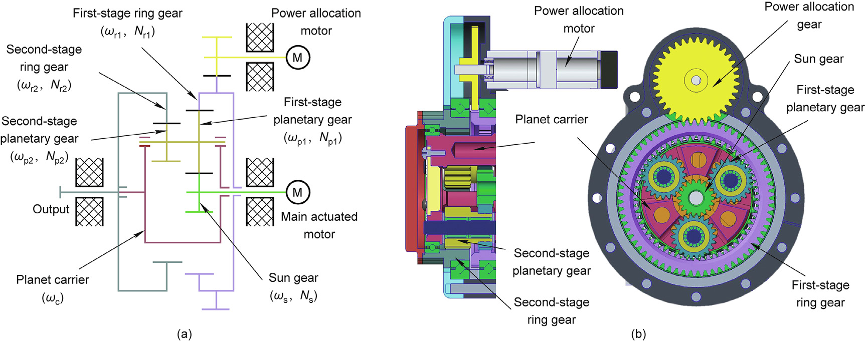
Fig. 1. Transmission connection diagram and structure of the proposed high-power-density variable transmission. (a) Transmission connection diagram; (b) transmission structure. M: motor.
The main power transmission system is based on the two-stage planetary reducer, which is small, lightweight, and reliable. We add a power allocation unit to this transmission system to control the first-stage ring gear’s rotational speed and thus enable adjustment of the reduction ratio.
In Fig. 1, ωr1 is the first-stage ring gear rotational speed, and Nr1 is the first-stage ring gear number of teeth. ωp1 and Np1 are the first-stage planetary gear rotational speed and number of teeth, respectively. ωr2 and Nr2 are the second-stage ring gear rotational speed and number of teeth, respectively. ωp2 and Np2 are the second-stage planetary gear rotational speed and number of teeth, respectively. ωs and Ns are the sun gear rotational speed and number of teeth, respectively. Finally, ωc is the planet carrier rotational speed.
From the transmission connection diagram shown in Fig. 1(a), we can determine the following relationships between the different transmission gears:
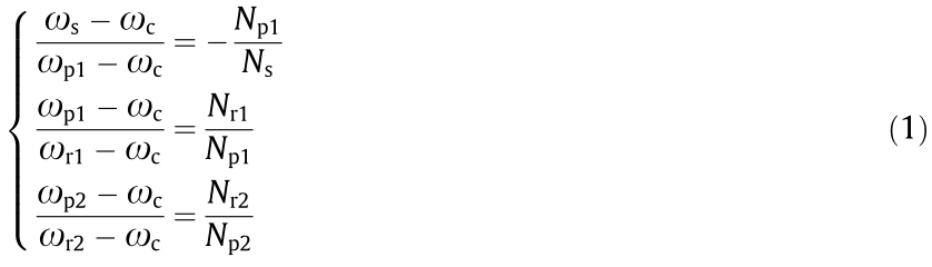
The first-stage planetary gear and the second-stage planetary gear are fixed on the same axle; therefore, we obtain ωp1 = ωp2. Using this relationship and Eq. (1), the reduction ratio i can then be calculated as follows:
If the first-stage ring gear is static (i.e., ωr1 = 0), then the system is a standard two-stage planetary gear train, and the reduction ratio ifixed is given by

from which Eq. (2) can be rewritten as follows:

We use the power allocation motor to control the speed of the first-stage ring gear and thus adjust the reduction ratio. From Eq. (4), we obtain the relationship between the reduction ratio i and the velocity of the first-stage ring gear. As shown in the results in Fig. 2, when the power allocation motor remains static, the system is then equivalent to the two-stage planetary gear train. When the velocity of the first-stage ring gear is equal to that of the sun gear, the system reduction ratio is 1. When the velocity of the firststage ring gear is higher than that of the sun gear, the system then becomes a speed-up gear. When ωr1 =  , the system’s output is static. The curve on the bottom left of the figure represents the inverted output state (i.e., where i < 0).
《Fig. 2》

Fig. 2. Relationship between the reduction ratio i and the velocity of the first-stage ring gear.
To implement the designed power allocation unit, we used a small power motor and a high-ratio gearbox. We selected these components because the actuator does not require peak speeds during most of its operation, and the power allocation motor therefore rarely consumes energy. Unlike systems that use dual motors to control the sun and ring gears of a planetary reducer [24,26], our power allocation motor is much smaller than the main actuator motor. Therefore, the energy efficiency of the proposed unit is higher than that of the previous dual motor systems, and there is no coupling between the two motors in the proposed system.
《2.2. Heat-dissipating structure》
2.2. Heat-dissipating structure
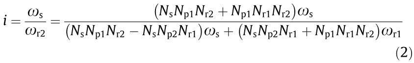
A major restriction that prevents high output power from being realized with electric actuators is heat accumulation, particularly at high currents. We therefore designed a heat-dissipating structure based on a composite PCM to remove the heat generated at high output power (Fig. 3). The composite PCM releases and absorbs energy during its phase transition to provide either heating or cooling, respectively. The transition is generally from a solid to a liquid phase, or vice versa.
As shown in Fig. 3, the bottom of the composite PCM container is in direct contact with the motor’s rotor, and the top of the composite PCM container is the actuator surface, which is exposed to the air. The selection of the composite PCM is dependent on the specific motor heating situation and the actuator’s operating environment. Legged robots emit heat intermittently and thus do not require additional cooling equipment.
《Fig. 3》
Fig. 3. Heat-dissipating structure based on the composite PCM.
The designed explosive electric actuator is shown in Fig. 4(a), along with a photograph of the real actuator (Fig. 4(b)). The actuator includes both the high-power-density variable transmission and the heat-dissipating structure. We developed an integrated design that merges the connection parts of the reducer and motor to reduce the number of components required and thus increase the actuator’s power density.
《Fig. 4》

Fig. 4. (a) Integrated design of the proposed explosive electric actuator and (b) photograph of the real actuator.
《3. Explosive power control》
3. Explosive power control
The proposed explosive electric actuator can output peak torque or peak speed instantaneously. However, continuous operation in the high-power state may damage either the actuator or the robot. We therefore propose an integral torque control method to achieve periodic and controllable high output power. We achieve effective power control by limiting the total output energy per unit time. The control performance is demonstrated using jumping experiments.
《3.1. Integral torque control method》
3.1. Integral torque control method
Low-ratio actuators can control their output force accurately via the motor current with high transparency. The torque integral of the actuator over a given time period can be expressed as follows:

where τ is the actuator torque,  is the given time period, I is the motor current, kT is the motor torque constant, and i is the reduction ratio. In a real-time controller, we can record the current and the reduction ratio in each period and then calculate the joint torque required to implement the following integral torque control method.
Industrial servo systems are oriented toward the production of their rated output in order to protect the motor from damage caused by overheating. Their controllers have strict peak current limits. However, this control strategy is unsuitable for use in legged robots during dynamic motion. In our design, the motors are often subjected to very high instantaneous currents.
We use the inertial hysteresis response characteristics of a lowpass filter (LPF) to control the actuator’s peak torque. The corresponding integral torque control method is shown in Fig. 5, where τ c is the continuous torque limit,τ p is the peak torque limit, τ t is the variable torque threshold, and τ filter is the equivalent integral of the actual actuator output torque τ actual. The actuator model shown in Fig. 5 is defined in Eq. (5). Using this model, we can transform the motor current into the actuator torque. Then, based on the flow diagram shown in Fig. 5, we can calculate the active torque limit τ lim required to constrain the torque command.
We set the initial value of τlim to τp and the corresponding value of τt to τc. As shown in Fig. 5, when the actual torque τactual is higher than τc over a given time period , the equivalent integral torque τfilter reaches τt, the output limit τlim is adjusted to τc, and τt is then adjusted to 0.9τc. When the actual torque τactual drops to τt for a while, the equivalent integral torque τfilter drops to τt, the output limit τlim is adjusted back to τp, and τt reverts to τc to allow the actuator to provide the high power output again.
We performed a simulation of the proposed integral torque control method, in which we set the peak torque limit at 300 N·m, the continuous torque limit at 100 N·m, and the power output time duration (T) to 1, 2, 3, or 4 s. During each control period, we input the desired torque τdesired (drawn as the green line in Fig. 6) and then ran the integral torque control method shown in Fig. 5. We calculated the equivalent integral of the actual output torque τfilter and then obtained the output limit τlim for the next period. The simulation results, which are shown in Fig. 6, demonstrate that the integral torque control method has a flexible parameter configuration and confirm that the method can control the maximum peak torque. We performed dynamic adjustment of τlim to control the integral torque of the actuator. This control method improves the instantaneous output power of the motor and protects the actuator from damage caused by excessive peak output.
《Fig. 5》
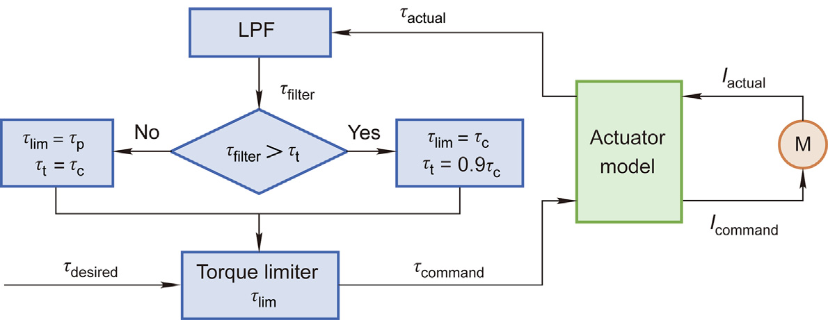
Fig. 5. Integral torque control method. Iactual: actual current; Icommand: command current; τcommand: command torque.
《Fig. 6》
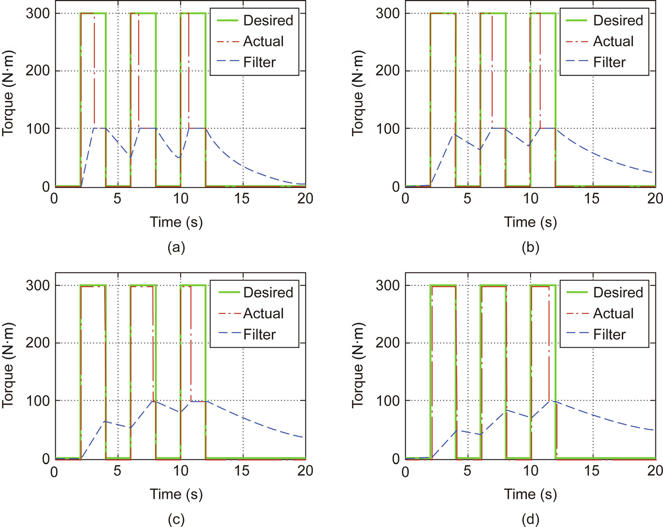
Fig. 6. Results of simulation of the integral torque control method. (a) T = 1 s; (b) T = 2 s; (c) T = 3 s; (d) T = 4 s.
《3.2. Explosive jumping control》
3.2. Explosive jumping control
Many legged robots use electric motors, parallel structures, and appropriate mechanical design to achieve ballistic and explosive motion [30–32]. To verify the effectiveness of the integral torque control method and the explosive electric actuator proposed in this work, we applied explosive jumping control to a single leg with two parallel actuators. The basic robot leg model (which is shown in the center of Fig. 7) is a symmetrical four-bar linkage mechanism with two actuators.
《Fig. 7》
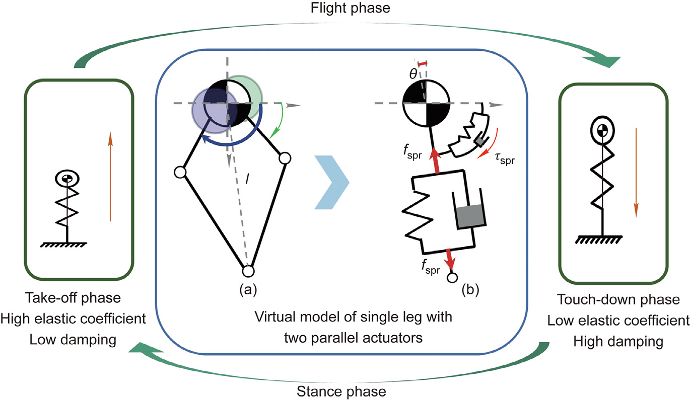
Fig. 7. Overview of the explosive jumping control strategy. (a) A simplified symmetrical leg model with one mass point at the top and a leg mechanism composed of two massless parallel links; (b) a virtual model of the symmetrical leg with a spring-damper system.  r: virtual force of the model; Tspr virtual torque of the model.
We use the integral torque control method in combination with virtual model control (VMC) to implement jumping control. To achieve jumping control, the VMC approach uses the actuator power to imitate virtual component effects, such as the effects of springs and dampers. Unlike a real spring, VMC can change the coefficient immediately in order to adapt both the take-off phase and the touch-down phase of the jumping motion. Fig. 7(a) shows a simplified symmetrical leg model with one mass point at the top and a leg mechanism composed of two massless parallel links, and Fig. 7(b) shows the virtual model of the symmetrical leg with a spring-damper system. The leg length  is controlled by the normal effect of the linear spring system, and the leg angle θ is controlled by the tangential effect of the torsional spring system. The virtual force and torque Tspr of the model shown in Fig. 7(b) can be expressed as follows:

where kvl and cvl are the stiffness and the damping coefficient for the virtual linear spring, respectively; kvt and cvt are the corresponding terms for the virtual torsional spring, respectively; and  are the actual and desired leg lengths, respectively (see the distance in Fig. 7(a)); and θ and θori are the actual and desired leg angles, respectively (see the angle θ in Fig. 7(b)).
The desired virtual force and torque are converted into the foot force of the robot, which can then be used to calculate the desired actuator torque. The desired virtual linear spring torque  is calculated as follows:

where  , T is transpose symbol; , Kv , and Cv are the virtual model parameters, vectors, or matrices in Eq. (6); and JP represents the Jacobian matrix between the actuator torque and the robot foot force, P represents polar coordinates. In general, we can control the robot leg to perform with different dynamic characteristics using the actuator’s torque.
Fig. 7 shows a schematic diagram of the explosive jumping control strategy. The different jumping phases are detected based on the leg length. The actuators provide explosive power with a high elastic coefficient during the take-off phase and high damping during the touch-down phase. This periodic and controllable explosive power output permits the robot leg to jump continuously.
《4. Experiment》
4. Experiment
《4.1. Proposed explosive electric actuator》
4.1. Proposed explosive electric actuator
We implemented the explosive electric actuator, as shown in Fig. 4. The diameter, length, and mass of the real actuator were 98 mm, 102 mm, and 1.3 kg, respectively. The reduction ratio of the two-stage planetary reducer (ifixed) was 29. The main actuated motor was designed by the authors. The peak torque of this motor was 10.55 N·m and the maximum rotation speed was 3000 r·min-1. The relationship between the speed of the first-stage ring gear and the reduction ratio for various sun gear speeds is shown in Fig. 8.
《Fig. 8》
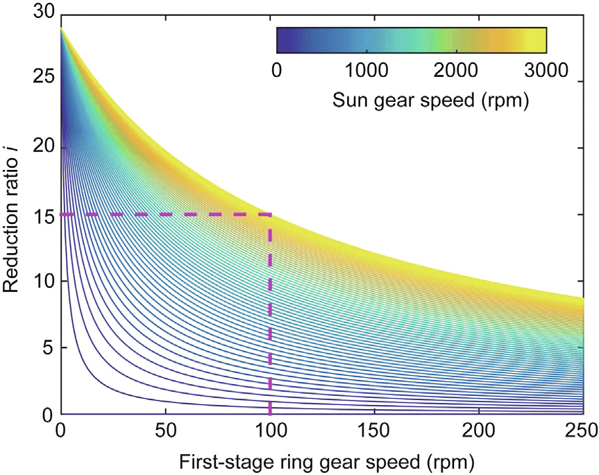
Fig. 8. Relationship between the first-stage ring gear speed and the reduction ratio for various sun gear speeds.
We used a Maxon ECX SPEED 16 M motor with a 186:1 reduction ratio planetary gearhead as the power allocation unit. To achieve fast and efficient conversion, we set the reduction ratio range to be from 15 to 29. As a result, the actuator peak output torque was approximately 305 Nm, and the maximum rotational speed was 200 r·min-1. In comparison with the actuator of the MIT Cheetah 3 [10], our explosive electric actuator is smaller in diameter and has a higher peak torque (Table 1); therefore, it is more suitable for use in multi-joint robot systems (e.g., humanoid robots) that have strict actuator size limitations.
《Table 1 》
Table 1 Comparison of actuators from our design and MIT Cheetah 3.

The designed prototype heat-dissipating structure based on the composite PCM is shown in Fig. 9(a). This structure is bonded to the motor stator housing. The structure has a gap with blocks to be filled with the composite PCM. The blocks are used to disperse the composite PCM in the gap. In this prototype, a transparent plastic shell and color blocks were used to allow us to see the phase change during temperature variations. In the real actuator, this structure is made of metal, and the composite PCM is colloidal at indoor temperatures, making it easy to assemble this structure. The mass of the structure is approximately 180 g, and the thickness is approximately 6 mm.
《Fig. 9》
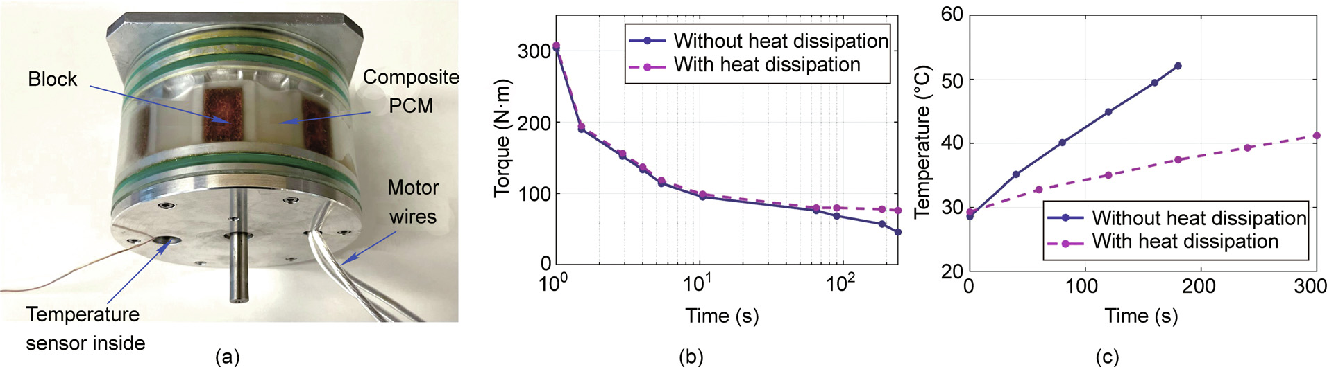
Fig. 9. Experimental testing of the heat-dissipating structure. (a) Photograph of the experimental heat-dissipating structure prototype based on the composite PCM; (b) peak torque duration; (c) temperature versus time characteristics.
We performed experiments to test the effectiveness of the heatdissipating structure shown in Fig. 9(a), where the temperature sensor is pasted onto the edge of the motor stator. Fig. 9(b) shows the results from the peak torque duration experiment. The maximum output torque (305 N·m) could be maintained for 1 s, and an output torque of 70 N·m could be maintained continuously. Fig. 9(b) shows that the heat-dissipating structure was incapable of increasing the instantaneous power because of the phase change time of the composite PCM. Fig. 9(c) shows the results from the temperature test. The heat-dissipating structure reduced the actuator temperature effectively. To summarize, although the heatdissipating structure did not increase the actuator’s instantaneous output power, it did reduce the heat accumulation. This result means that the heat-dissipating structure is acceptable for use in legged robots, which do not operate continuously at high output power during dynamic motion.
To implement force control directly via the actuator current, we measured the current and the torque of the proposed actuator under various working conditions; the results are shown in Fig. 10. Based on these results, we consider the proposed actuator to be sufficiently linear. However, there was still some friction present in the reducer. At high currents (> 50 A), the output torque was less linear than the torque at low currents; this was mainly caused by the nonlinearity of the motor, which led it to deviate from its rated state during operation. To overcome this problem, we used the fitting result and revised the nonlinearity at high currents according to the motor parameters.
《Fig. 10》
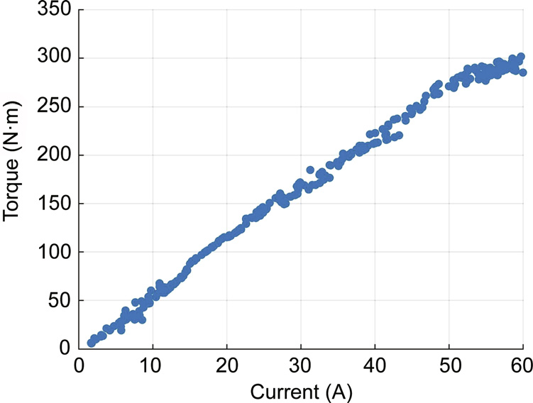
Fig. 10. Measured torque versus current characteristics for the actuator.
《4.2. Actuator performance in the jumping experiment》
4.2. Actuator performance in the jumping experiment
To evaluate the performance of the proposed actuator when used in a legged robot, we designed a single symmetrical robot leg based on the model described in Section 3.2. The symmetrical leg contains two parallel actuators that rotate relative to the trunk base frame. To reduce the mass of this leg, we used carbon fiber tubes as the leg links and aluminum parts to form the joint connections. We limited the movement of this robot leg using vertical slide guides in order to realize vertical jumping.
In the jumping experiment, the robot took off with a high elastic coefficient and touched down with high damping. The actuators produced explosive power for the take-off and reactive power for the touch-down. The mass of the robot leg was 5.2 kg, with a 3 kg load on top. The initial leg length was 0.42 m, the desired take-off leg length was 0.67 m, and the desired touch-down leg length was 0.55 m. In this experiment, the virtual linear spring stiffness kvl was 1800 N∙m-1 , and the virtual damping coefficient cvl was zero during the take-off phase. In the touch-down phase, kvl was 1000 N∙m-1 , and cvl was 30 N∙sm-1 . Snapshots of the experiment are shown in Fig. 11. The legged robot maximum jump height was 1.5 m (from floor to toe).
《Fig. 11》

Fig. 11. Snapshots of jumping experiment with legged robot. The maximum jump height was 1.5 m.
Fig. 12 shows the reduction ratio, the torque, and the velocity of the first joint actuator during the continuous jumping experiment with a legged robot. The results obtained for two jumps are plotted here to verify that the actuator can provide explosive power periodically. Fig. 12(a) shows the reduction ratio curve. To acquire the high speed required during take-off and then absorb the impact during touch-down, the reduction ratio was reduced to allow the actuator to output a higher speed. Figs. 12(b) and (c) show the actual torque and velocity curves for the jumping experiment, respectively. A slight oscillation was observed in the curves during impact. During the reduction ratio adjustment, the peak torque and the peak velocity did not overlap. The integral torque control method limited the peak torque and thus allowed the actuator to provide explosive power periodically.
《Fig. 12》

Fig. 12. (a) Reduction ratio, (b) torque, and (c) velocity of the first joint actuator during the continuous jumping experiment with a legged robot.
In general, to accelerate at the beginning of the jumping motion, the robot requires the actuators to provide a high torque output; to jump high at the moment of take-off, the robot requires the actuators to provide high speed. It is thus difficult for the constant reduction ratio reducer to eliminate the tradeoff between high torque and high speed during the jumping motion. In our jumping experiment, we selected the reduction ratio range of the joints and then calculated the transform threshold in the simulation. In the real robot experiment, we used a threshold that included the torque and speed values during motion to trigger variable transmission; the power allocation motor then changed speed smoothly to enable continuous adjustment of the reduction ratio. In future work, we will study the complex real-time reduction ratio adjustment method further in order to adapt to other types of highly dynamic motion.
To verify the advantages of the variable transmission, we present a map of the absolute values of the speed and torque in Fig. 13. The figure shows the torque-speed range of the main actuated motor that was introduced in Section 4.1 for different reduction ratios. The range covered by the blue line represents a reduction ratio of 29, which has high torque and low speed. The range covered by the green line represents a reduction ratio of 15, which has low torque and high speed. The variable transmission designed in this work changed the reduction ratio (indicated by the magenta asterisks) to cover all the green, blue, and magenta ranges. The absolute values of the speed and torque recorded (in the period from 0–2 s shown in Figs. 12(b) and (c)) in the legged robot jumping experiment are also shown in the figure. Fig. 13 shows that the designed actuator can provide the high peak speed and high peak torque that are required during the jumping experiment when using variable transmission.
《Fig. 13》
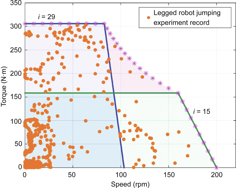
Fig. 13. Map of absolute values of the speed and torque.
《4.3. Quadruped and humanoid robot jumping experiment》
4.3. Quadruped and humanoid robot jumping experiment
We applied the proposed actuator to both quadruped and humanoid robots to provide the explosive power required for dynamic jumping. For the legs of the quadruped robot, we used the same structure that was described in Section 4.2; we used the proposed actuators for the hip and knee joints of each leg. The robot’s mass was 37 kg. We built the VMC method based on the quadruped robot’s center of mass (CoM) to conduct the jumping experiment. We set the CoM height to have the same value as the length of the single-legged robot in Section 4.2. We calculated each joint’s torque during the jumping motion using foot force optimization and a Jacobian matrix. Snapshots of the jumping experiment performed with this robot are shown in Fig. 14. The maximum jump height was more than 0.8 m. The joints showed similar performance to that of the single-legged robot, because they both had the same leg structure. Fig. 14 shows that the pitch angle increased continuously after take-off, which resulted from the deviation between the robot’s CoM and the body’s geometric center. The Swiss Federal Institute of Technology in Zurich (ETH) SpaceBok robot used a reaction wheel integrated inside its main body to adjust its rotation during jumping [30]. In future work, we will implement a posture stabilizer. The jumping experiment results confirm that multiple actuators can be used simultaneously to output explosive speed and torque in the system. Therefore, the proposed explosive electric actuator and the associated control method are suitable for application to the dynamic motion of legged robots.
《Fig. 14》

Fig. 14. Snapshots of the quadruped robot jumping experiment. The maximum jump height was 0.8 m.
Provision of a jumping capability is important to improve the performance of humanoid robots in various applications. The Atlas robot, which uses hydraulic actuators, is capable of jumping [4]. However, it is difficult for humanoid robots powered by electric actuators to jump, because most of these electric actuators cannot supply the required explosive power.
We applied the proposed actuator to the hip joints of a humanoid robot to allow it to perform jumping. The robot’s mass was 45 kg, and its height was 1.7 m. Using the characteristics of the proposed actuator, we optimized the robot’s initial posture to maximize the initial acceleration for jumping; we then generated the trajectory of the CoM to make the planned jumping motion more efficient. We considered the full-body dynamics in order to track the trajectory using virtual force control [33]. Snapshots of the jumping experiment performed with this robot are shown in Fig. 15. The jump height exceeded 0.5 m. In the experiment, the initial height of the robot was 1.2 m, and the pitch angle was approximately 27°. The reduction ratio of the hip joint actuator changed from 25 to 20 during the jumping motion. The actuator’s maximum output torque was approximately 252 Nm at the beginning of the jump, and the actuator’s maximum output speed was 117 rpm during the take-off phase. These results confirm that the proposed explosive electric actuator can support a humanoid robot and allow it to perform a dynamic jumping motion.
《Fig. 15》
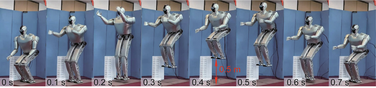
Fig. 15. Snapshots of the humanoid robot jumping experiment. The maximum jump height was 0.5 m.
《5. Conclusions》
5. Conclusions
Unmanned systems such as legged robots require explosive actuators to perform dynamic motion in complex environments. This paper proposed an explosive electric actuator and an associated control method for legged robots. The proposed highpower-density variable transmission allows continuous and efficient adjustment of the ratio of the speed to the torque output to provide high peak speed or high peak torque at specific moments during dynamic motion. A heat-dissipating structure based on a composite PCM effectively removes the heat that accumulates during high-power operation. The integral torque control method achieves periodic and controllable output power. In the experiments, single-legged, quadruped, and humanoid robots reached jump heights of 1.5, 0.8, and 0.5 m, respectively. These values are the highest reported to date for legged robots powered by electric actuators.
Legged robots have various physical forms; hence, it is difficult to design an actuator that will be suitable for all such robots. This paper proposed a general design method to meet the explosive output requirements of most legged robots. This method can be adjusted according to the specific system demands. The actuator characteristics should match the desired system performance. Optimization of the actuator output power for legged robots will be a subject worthy of future study.
《Acknowledgments》
Acknowledgments
This work was supported by the National Key Research Program of China (2018YFB1304500) and the National Natural Science Foundation of China (91748202 and 62073041).
《Compliance with ethics guidelines》
Compliance with ethics guidelines
Fei Meng, Qiang Huang, Zhangguo Yu, Xuechao Chen, Xuxiao Fan, Wu Zhang, and Aiguo Ming declare that they have no conflict of interest or financial conflicts to disclose.


 京公网安备 11010502051620号


