

《1. Introduction》
1. Introduction
Wellbore instability [1] is a serious drilling problem that significantly increases the costs and affects the safety and efficiency of drilling engineering. This problem is more common when drilling in a shale formation with water-based drilling fluid (WBF). This is because shale is generally rich in clay minerals, which hydrate and swell when in contact with water, resulting in several wellbore-instability phenomena such as wellbore collapse, a tight hole, and stuck pipes. In addition, nanoscale and microscale pores or fractures are well developed in shale [2–4]. The invasion of drilling fluid into the shale formation through these tiny channels further aggravates shale hydration.
The hydration of shale [5] is essentially the hydration of clay minerals, which results from two distinct mechanisms: surface hydration [6,7] and osmotic hydration [8]. Surface hydration causes crystalline swelling in two ways: First, the silicate clay surface adsorbs water molecules directly through hydrogen bonding; and second, adsorbed cations near the surface adsorb water molecules. Surface hydration can occur in all types of clay minerals, causing a small degree of swelling (1.0–2.2 nm) but a very high hydration swelling pressure [6,7,9]. Osmotic hydration is only limited to expansive clays. The concentration of cations in the interlayers is higher than that in the surrounding water, so water enters the interlayers to restore cation equilibrium. This type of hydration can lead to a significantly larger increase in volume (2–13 nm) [7,10].
With the aim of reducing hydration-induced wellbore instability, shale inhibitors are utilized to decrease the interaction between the drilling fluid and shale; such inhibitors include salts [11,12], poly alcohols [13], amines [14,15], nanomaterials [16], and surfactants [17,18]. The most commonly used shale inhibitor is potassium chloride (KCl) [11]. Because K+ has a low hydration energy, it can migrate to the interlayer spaces of clays while remaining bound to the clay surface, forming a stable structure. The wellbore wall is an ideal semi-permeable membrane, so high-concentration or even saturated inorganic and organic salts with low water activity can effectively decrease water invasion and inhibit hydration [19]. Poly alcohol inhibitors can be phase separated and adsorbed onto the well wall to prevent water invasion when the temperature exceeds their cloud points, which assists in stabilizing shale and inhibiting hydration (referred to as ‘‘shale inhibition”). Polyether amine has been studied intensively as a high-performance shale inhibitor. It enters the clay interlayers and is strongly adsorbed onto the clay by means of hydrogen bonding and/or electrostatic attraction. Nanomaterials such as nano-SiO2 [20] and laponite [16] are also beneficial for shale inhibition due to their strong adsorption ability, poreplugging performance, and so forth. Surfactants with long carbon chains [21,22], amidocyanogen silanol [23], and ionic liquids [24] can change the contact angle and weaken the adsorption of water onto the rock surface, but they have a limited ability to modify wettability. Usually, the contact angle cannot reach more than 90 degrees
An increasing number of researchers have realized that surface hydration with a small swelling volume can produce a high swelling pressure, leading to shale disintegration and severe wellbore instability [25,26]. Nevertheless, most shale inhibitors are aimed at inhibiting osmosis hydration since the inhibiting performance of surface hydration is difficult to evaluate. Increasing the contact angle can reduce the free energy of the shale surface. From a thermodynamic point of view, this can decrease the driving force of the adsorption of water, thereby reducing surface hydration. Based on this theory, this paper reports on the synthesis of hydrophobic nano-silica (HNS) from nano-silica and a long-chain quaternary ammonium salt and its use to increase the contact angle of shale. The wellbore-strengthening performance of HNS is comprehensively studied and the mechanism is analyzed. The approach described herein may provide an avenue for inhibiting both the surface hydration and the osmotic hydration of shale.
《2. Materials and methods》
2. Materials and methods
《2.1. Materials》
2.1. Materials
SiO2 nanoparticles (20 nm), stearyl trimethyl ammonium chloride (STAC; 98 wt%), ethanol (99.5 wt%), and KCl (99.5 wt%) were purchased from Aladdin Reagent Co., Ltd. (China). Polyether amine (D230, 99 wt%) was purchased from BASF (Germany). Bentonite was provided by China National Petroleum Corporation Engineering Technology Research and Development (R&D) Co., Ltd. (China). Two kinds of shale samples were used in this research. One was a water-sensitive outcrop shale sample, which was obtained from Guanghan City in Sichuan Province, China. This type of shale has a low recovery in water in the hot-rolling recovery test. The other was a brittle shale sample, which was taken from an outcrop of the Longmaxi formation in Sichuan Province. The detailed mineralogical compositions of the two shale samples were determined by X-ray diffraction (XRD) analysis, and the results are presented in Table 1.
《Table 1》
Table 1 Mineralogical composition of the shale samples analyzed by XRD.

《2.2. Preparation of hydrophobic nano-silica》
2.2. Preparation of hydrophobic nano-silica
The preparation route of HNS is described in Fig. 1. Certain amounts of water and ethanol were mixed well in a beaker. Nano-SiO2 was then dispersed into the solution using an ultrasonic disperser. The above mixture was transferred into a three-necked, round-bottomed flask and heated to 70 °C in a water bath. STAC was then added to the flask. The reaction was carried out for 6 h at 70 °C with stirring at 300 r∙min–1 . When the reaction was complete, the ethanol and part of the water were removed by means of a vacuum distillation device to bring the solid content of the product up to 20%. The HNS mentioned in this paper refers to this modified silica emulsion with a solid content of 20%.
《Fig. 1》
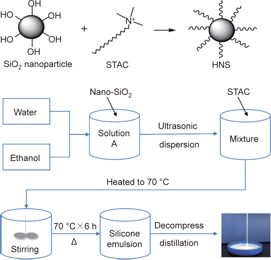
Fig. 1. The chemical reaction formula to synthesize HNS and the synthesis procedure.
《2.3. Characterization of hydrophobic nano-silica》
2.3. Characterization of hydrophobic nano-silica
The particle-size distributions of the nano-SiO2 and HNS were measured using a Zetasizer Nano ZS (Malvern Instruments Ltd.; UK). The morphology of the HNS was studied using high-resolution transmission electron microscopy (TEM, Tecnai G2 F20, FEI; USA).
《2.4. Wellbore-strengthening performance》
2.4. Wellbore-strengthening performance
2.4.1. Linear swelling test
The degree of linear swelling is an important parameter for evaluating the extent of hydration expansion in clay minerals. First, bentonite pellets (about Φ25 mm × 9.5 mm) were prepared by compressing 10 g of dry bentonite powder under 10 MPa pressure for 5 min using a hydraulic press and a cylinder mold. Next, the bentonite pellets were immersed in water and in solutions of different inhibitors, respectively, and the linear swelling heights of the pellets in each liquid were measured using a CPZ-2 dualchannel linear swelling meter (Tongchun; China).
2.4.2. Hot-rolling recovery test
The hot-rolling recovery test is a standard experiment of the American Petroleum Institute (API) [27], which evaluates the degree of dispersion of shale cuttings in a certain type of liquid at high temperatures. For this test, the water-sensitive outcrop shale sample was used. First, shale cuttings (20 g) sized between 6 and 10 mesh and 350 mL of inhibitive solution were poured into a stainless steel aging cell. Then, the aging cell was hotrolled in a GW300-PLC roller oven (Tongchun) at a certain temperature for 16 h. After being cooled to room temperature, the remaining cuttings were screened with a 40 mesh sieve. Finally, the recovered cuttings were dried at 105 °C for 4 h and weighed. The shale recovery, Rs, was calculated by Eq. (1). Each test was repeated five times.

where m1 represents the mass of the shale cuttings before hotrolling (g) and m2 is the mass of the recovered dry shale cuttings (g).
2.4.3. Compressive strength test
The compressive strength test is used to quantitatively analyze the strength changes in shale samples after they have been immersed in different solutions. Cylindrical cores (Φ25 mm × 50 mm) were processed using the brittle outcrop shale samples. Five cores were placed in the same aging cell with 250 mL of deionized (DI) water or inhibitive solution, respectively. The aging cells were then placed in a heating oven at 120 °C for 72 h. After cooling, the cores were taken out and allowed to dry naturally. A microcomputer-controlled rock triaxial test machine (TAW-100, Changchun Chaoyang Test Instrument Co.; China) was then used to analyze the compressive strengths of the five cores. The mean compressive strength was calculated using Eq. (2).

where  is the mean compressive strength (MPa), i is the index of summation, P is the failure load of the tested core (N), and A is the cross-sectional area (mm2 ).
《2.5. Mechanism analysis》
2.5. Mechanism analysis
2.5.1. Particle-size distribution and zeta potential of the bentonite suspension
Bentonite powder (24 g) was dispersed in 600 mL of DI water and stirred for 24 h. Five quantities of HNS (0, 0.5, 1.0, 1.5, and 2.0 g) were added to five 100 mL bentonite suspensions, respectively. The mixtures were then stirred at 300 r∙min–1 for 24 h. The particle-size distribution and zeta potential of the bentonite suspensions with different HNS concentrations were determined using a Zetasizer Nano ZS 90 (Malvern Instruments Ltd.; UK).
2.5.2. Surface tension of hydrophobic nano-silica suspension
The surface tensions of the HNS suspensions with various concentrations were determined with the Wilhelmy Plate method [28] using a DCAT21 tensiometer (Dataphysics; Germany) at room temperature.
2.5.3. Contact angle measurement
Thin shale slices with a thickness of 2–4 mm were prepared by cutting the brittle shale sample using a wire cutting machine. The shale slices were placed into aging cells and immersed in 250 mL of HNS suspension of different concentrations. The aging cells were then aged for 16 h at 120 °C. After that, the shale slices were taken out and dried using an electric oven at 102 °C. The contact angles of the DI water on the surfaces of the shale slices were analyzed using an OCA 25 type contact angle measuring device (Data Physics).
2.5.4. Morphology
A scanning electron microscope (SEM; Hitachi S-4800; Japan) was used to study the micromorphology of the shale slices’ surface after contact angle measurement. The morphology changes of the shale cuttings before and after hot-rolling in HNS suspensions were also observed.
2.5.5. Calculation of surface free energy
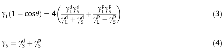
Surface free energy is the root cause of shale surface hydration, so reducing the surface free energy of shale is the most fundamental way to inhibit surface hydration. The contact angle method (also known as the Wu method [29]) was used to calculate the surface free energy changes of the shale before and after treatment with D230 and different concentrations of HNS. First, the contact angles of the DI water and diiodomethane on the shale surfaces were measured. Then, the data were substituted into the model of the Wu method (Eq. (3)). In this way, the dispersion component  of the surface free energy and the polar component
  of the surface free energy were obtained. Finally, the surface free energy
  was calculated according to Eq. (4). The surface tension components of the liquids used are presented in Table 2.
where θ is the contact angle (° ),  is the liquid surface tension (mJ·m–2 ), and
  and
and  are the dispersion and polar components of , respectively (mJ·m–2 ).
  is the surface free energy of a solid (mJ·m–2), and
 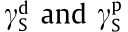 are the dispersion and polar components of , respectively (mJ·m–2 ).
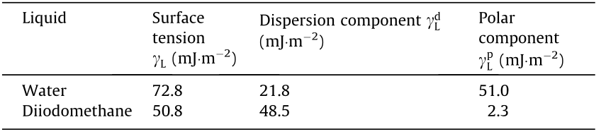
《Table 2》
Table 2 Values of surface tension and its dispersion and polar components for water and diiodomethane.
《3. Results and discussion》
3. Results and discussion
《3.1. Characterization of hydrophobic nano-silica》
3.1. Characterization of hydrophobic nano-silica
HNS was synthesized by modifying nano-SiO2 using an anionic surfactant, STAC (Fig. 2). HNS is a viscous silicone emulsion with a certain fluidity, as shown in Fig. 2(a). The morphology of the nanoSiO2 and HNS was observed by means of TEM. The experimental results are shown in Fig. 3. Before the modification, the SiO2 nanoparticles were uniformly distributed without aggregation (Figs. 3(a) and (b)). After the modification, small aggregates with a wide particle-size distribution were observed, with each aggregate consisting of several to dozens of SiO2 nanoparticles (Figs. 3(c) and (d)). The particle-size distributions of the nano-SiO2 and HNS were measured using the dynamic light-scattering method, and the results are shown in Fig. 2(b). The unmodified nano-SiO2 has a narrow particle-size distribution, with a z-average particle size of 19.39 nm. In comparison, the particle size of HNS is in the range of 100–900 nm, and the z-average value is 283 nm, which is the particle size of the silica aggregates rather than that of individual silica particles. The experimental data from the laser particle-size experiments are in good agreement with the particle-size distribution observed via TEM.
《Fig. 2》

Fig. 2. The appearance of HNS sample and its particle size distribution. (a) A picture of the HNS sample; (b) particle-size distribution of nano-SiO2 and HNS, as measured by the dynamic light-scattering method. PDI: polydispersity index.
《Fig. 3》

Fig. 3. TEM images of (a, b) untreated nano-SiO2 and (c, d) hydrophobic-modified nano-SiO2.
《3.2. Performance of hydrophobic nano-silica》
3.2. Performance of hydrophobic nano-silica
The wellbore-strengthening performance of HNS was studied using the following three evaluation methods: the linear swelling test, hot-rolling recovery test, and compressive strength test of shale.
3.2.1. Linear swelling test
The hydration and expansion of clay minerals in shale formation is an important reason for instability of the wellbore wall. The linear swelling test can evaluate the performance of HNS in inhibiting hydration and instability by precisely measuring the swelling height of the clay in aqueous solutions. Fig. 4 shows the linear swelling heights of bentonite pellets immersed in water, 5 wt% KCl, 2 wt% polyether amine D230, and 1 wt% HNS, respectively. As shown in Fig. 4, the linear swelling height of the bentonite pellets immersed in water increased rapidly. After testing for 24 h (1440 min), the linear swelling height in water reached 7.45 mm. In contrast, the linear swelling heights of the bentonite pellets in 5 wt% KCl, 2 wt% D230, and 1 wt% HNS were 6.07, 6.55, and 5.95 mm, respectively. Of these, the linear swelling height in the HNS suspension was the lowest, indicating that HNS is more effective than KCl and D230 at inhibiting the hydration and swelling of clay minerals, and is thus more beneficial to wellbore stability during drilling.
《Fig. 4》
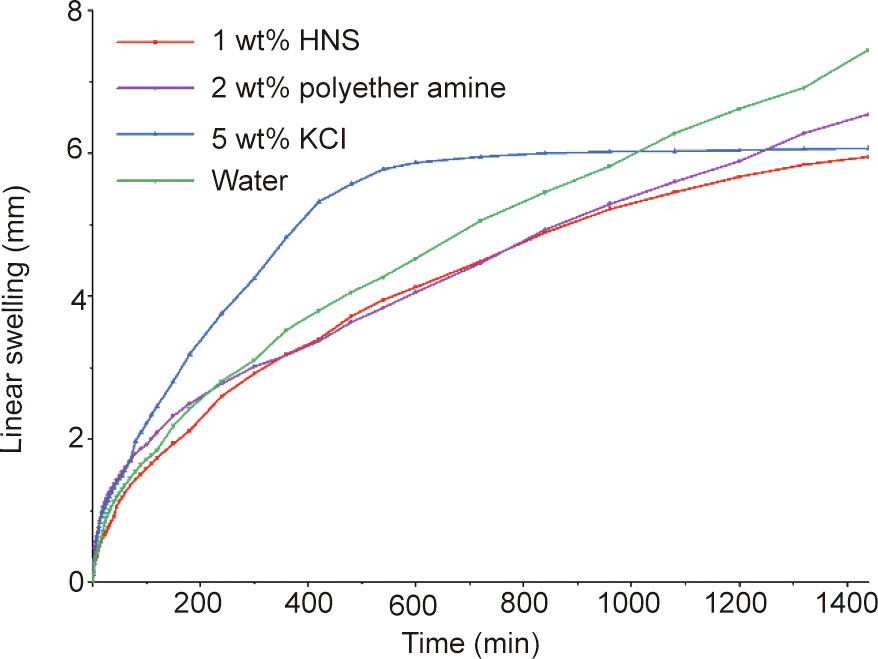
Fig. 4. Linear swelling curves of bentonite pellets in water and various inhibitive solutions.
3.2.2. Hot-rolling recovery test
The hydration of minerals in a shale formation easily leads to sloughing or wellbore collapse. The hot-rolling recovery test was used to evaluate the ability of HNS to prevent collapse.
Fig. 5 presents the shale cutting recovery of water and different inhibitive solutions after hot-rolling at 120 °C for 16 h. The Rs percentage of DI water was merely 6.8%, which demonstrates that the shale cuttings are extremely water sensitive. The commonly used shale inhibitor KCl cannot effectively inhibit the hydration of shale, as the shale recoveries were only 8.4% and 11.2% for 5 wt% and 7 wt% KCl, respectively. For 1 wt% D230, the Rs was 57.5%, which suggests that polyether amine can inhibit shale hydration to some extent. The surfactant STAC has no inhibiting performance, since its Rs was merely 3.1%. Unmodified nano-SiO2 was found to improve the Rs by 26.3%. However, the STAC-modified nano-SiO2 (i.e., HNS) had a substantially higher Rs than KCl, raw nano-SiO2, or D230. For 1 wt% HNS suspension, the shale recovery was as high as 85.2%, indicating that HNS is capable of preventing the hydration and dispersion of shale in an aqueous medium.
《Fig. 5》
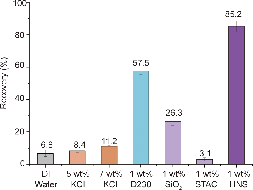
Fig. 5. Shale cutting recoveries of water and various aqueous solutions with different concentrations.
3.2.3. Compressive strength test
A compressive strength test of shale is a direct way to evaluate the wellbore-strengthening performance of HNS. The compressive strengths of untreated shale cores and the shale cores treated by HNS suspensions were tested, and the results are shown in Fig. 6. The original core with the greatest compressive strength of 183.82 MPa was the outcrop taken from Sichuan Province. The compressive strength of this core was significantly reduced to 134.49 MPa after the hot-rolling treatment by water. It was found that the cores treated with HNS suspensions had greater compressive strengths than the core treated with water. With an increase in HNS concentration, the compressive strengths of the cores also increased. When the HNS concentration was 3 wt%, the strength of the core increased to 186.69 MPa, which was slightly greater than that of the original core. This finding shows that HNS can prevent the decrease of rock strength—or even increase it at higher concentrations—during drilling.
The three experiments described above show that HNS is effective in stabilizing a wellbore by reducing shale hydration and slowing down the decrease of rock strength.
《Fig. 6》

Fig. 6. Compressive strengths of untreated shale cores and shale cores treated by DI water and HNS suspensions at 120 °C for 72 h.
《3.3. Mechanism》
3.3. Mechanism
3.3.1. Zeta potential measurement
The interaction between HNS and clay minerals is the fundamental cause of adsorption and what determines a good wellbore-strengthening performance. Electrostatic interaction is a driving force for the adsorption of HNS onto the surface of clay minerals or shale, since clay is negatively charged and HNS is positively charged. The zeta potential test examined the electrostatic attraction between HNS and bentonite.
The zeta potentials of the HNS suspension at different concentrations were tested. As the concentration increased from 0.5 wt% to 2.5 wt%, the zeta potential increased from 27.2 to 34.8 mV (Fig. 7 (a)), which demonstrated that HNS is composed of positively charged nanoparticles.
Due to the lattice defects caused by lattice substitution during the natural formation process of clay minerals, clay minerals are negatively charged [6,7]. As shown in Fig. 7(a), the zeta potential of bentonite was found to be –21.1 mV. When HNS was added, the zeta potential of bentonite increased from –20.6 to –13.4 mV as the concentration of HNS increased from 0.25 wt% to 2 wt%, indicating that HNS neutralizes part of the negative charge of bentonite. Thus, the zeta potential test demonstrated the existence of electrostatic attraction between HNS and bentonite.
According to electrostatic stability theory, the addition of HNS weakens the double-layer repulsive force and thus decreases osmotic hydration. Clay particles tend to aggregate, resulting in an increase in particle size. As shown in Fig. 7(b), the D50 of bentonite increased from 4.56 to 30.0 μm when the concentration of HNS increased to 1.0 wt%, which demonstrates the capability of HNS to inhibit osmotic hydration.
《Fig. 7》
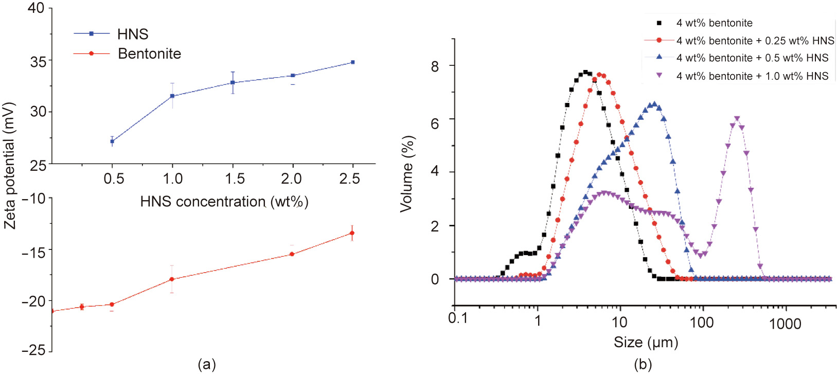
Fig. 7. The influence of HNS on the (a) zeta potential and (b) particle size of 4 wt% bentonite suspension.
3.3.2. Contact angle, shale surface morphology, and surface free energy
3.3.2.1. Contact angle. After treatment with HNS at 120 °C for 16 h, a layer of nanoparticles (shown in white) was adsorbed onto the surface of the shale slices, as shown in Fig. 8. As the concentration of HNS increased, the adsorbed amount also increased. The contact angles of the DI water on the original shale and on the shale slices treated with 1 wt% HNS, 2 wt% HNS, and 3 wt% HNS were 13.4°, 143.7°, 102°, and 110°, respectively. It is clear that the contact angle was reversed from hydrophilic to hydrophobic after the treatment of HNS. When the concentration of HNS was 1 wt%, the contact angle was very close to that of a super hydrophobic surface (>150°). The reason for the decrease in contact angle at higher concentrations of HNS might be that the roughness of the shale increases when the adsorbed amount is larger.
《Fig. 8》

Fig. 8. The film-forming effect and contact angles of DI water on original shale and on shale treated by 1 wt% HNS, 2 wt% HNS, and 3 wt% HNS.
Micropores and microfractures are well developed in shale formations. Therefore, in the drilling process of a shale reservoir, the capillary action is relatively large, causing the shale to absorb water and ultimately reducing the strength of the wellbore wall. As shown in Eq. (5), capillary force is related to the contact angle and surface tension. According to the results of the surface tension test, HNS has no effect on the surface tension of water. After HNS treatment, the shale surface became hydrophobic, and the capillary action became resistance to water invasion, which is beneficial for improving the stability of the wellbore wall.

where PC is the capillary pressure (Pa), σ is the surface tension (mN∙m–1 ), θ is the contact angle of water on the shale (°), and r is the inner diameter of the capillary tube.
3.3.2.2. Surface morphology of shale. The surface morphology of the original shale slice and the shale slice after treatment with 1.0 wt% HNS was observed by means of SEM. As shown in Figs. 9(a) and (b), there are many micron-sized particles on the surface of the original shale slice. After treatment with 1 wt% HNS, a layer of nanoparticles was adsorbed onto the shale surface, thereby artificially fabricating a micro-nano structure on the surface of the shale (Fig. 9(c)). At higher magnifications, nanoscale particles can be clearly observed, as shown in Fig. 9(d). This micro-nano hierarchical structure is similar to the surface structure of the lotus leaf (Figs. 9(e) and (f)), which is extremely hydrophobic; thus, the shale structure gains a hydrophobic effect.
《Fig. 9》

Fig. 9. SEM images of the surface of (a, b) the original shale; (c, d) the shale treated with 1.0 wt% HNS at 120 °C for 16 h; and (e, f) a lotus leaf.
The reason why lotus leaves are superhydrophobic has been reported many times in the literature [30,31]. Fig. 10(a) depicts a schematic diagram of the superhydrophobic mechanism of the lotus leaf surface. First, there are many micron-sized papillae on the surface of the lotus leaf. Second, the surface of the lotus leaf, including the surface of the papillae, is superimposed by a very dense layer of nano-sized wax tubules. Thus, the lotus effect is a combination of chemical hydrophobicity (the waxy component on the leaf) and physical patterns (a micro-nano hierarchical structure). The untreated surface of the shale has micron-sized particles; after treatment with HNS, which is chemically hydrophobic, the surface of the shale formed a lotus-leaf-like structure, resulting in a strong hydrophobic effect. In this research, the contact angle was tested under air conditions. According to the Cassie–Baxter model (Fig. 10(b)), air is trapped under the water droplet and acts as an important factor in forming a superhydrophobic surface [32]. However, there is no air underground (except in gas reservoirs) in drilling engineering. Therefore, more investigation is required on the wettability of surfaces under water conditions.
《Fig. 10》
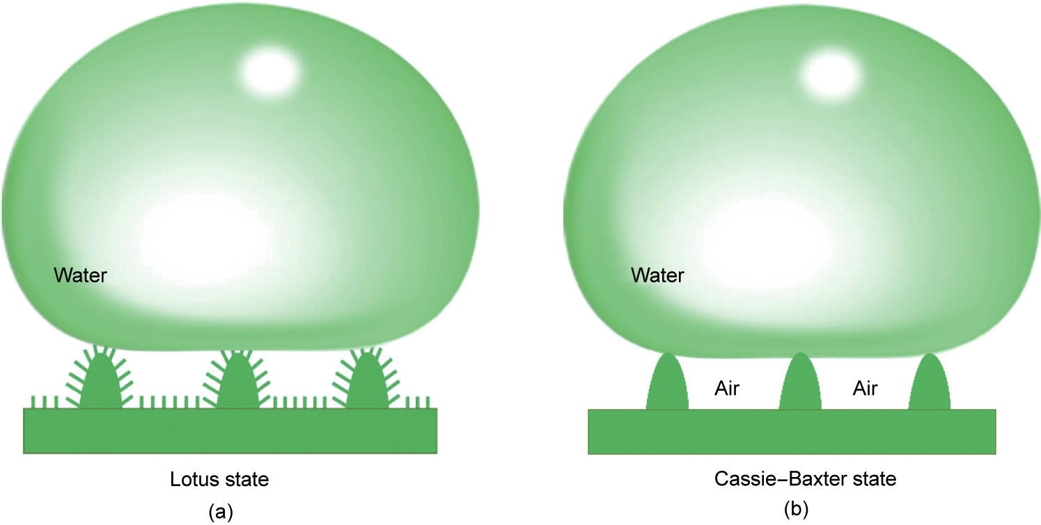
Fig. 10. Schematic of a liquid drop under (a) the lotus state and (b) the Cassie-Baxter state.
3.3.2.3. Surface free energy. The contact angles of the DI water and diiodomethane on the modified shale surfaces were measured, and the results are shown in Table 3. The surface free energy was calculated as described in Section 2.5.5, and the results are presented in Table 4. It can be seen that the surface free energy of the original shale was 80.83 mJ·m–2 . After treatment with 1 wt% D230, the surface free energy was slightly reduced. However, after treatment with HNS, the surface free energy was significantly reduced at the studied concentrations.
《Table 3》
Table 3 Contact angles of DI water and diiodomethane on the untreated shale surface and on the shale surfaces treated with 2 wt% D230 and with HNS with different concentrations.

《Table 4》
Table 4 Surface free energy and its components for the untreated shale and the shale treated by D230 and HNS.
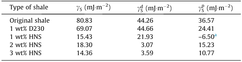
a Because the Wu method is not universal, the polar component of the shale treated by 1 wt% HNS might be meaningless since it is negative.
The surface free energy is the driving force of water adsorption, so reducing the surface free energy of shale is the fundamental way to inhibit surface hydration. Shale has a relatively large surface free energy and a strong ability to adsorb water molecules from drilling fluids during the drilling process. After HNS treatment, the surface free energy of the shale was significantly reduced. The adsorption capacity of water was thus also substantially reduced, thereby effectively inhibiting the surface hydration of shale from the perspective of thermodynamics. In comparison, the widely used shale inhibitors KCl and polyether amines lack the capability to inhibit surface hydration.
3.3.3. Micromorphology of shale cuttings
After hot-rolling, the recovered shale cuttings were observed by SEM. The SEM images of the original shale cuttings and of the shale cuttings after hot-rolling in 0.5 wt% HNS and 1.0 wt% HNS suspension are shown in Fig. 11. As shown in Figs. 11(a) and (b), there were abundant micropores in the original shale cuttings, which provide channels for water invasion. However, the morphology of the shale cuttings clearly changed after treatment with 0.5 wt% HNS and 1.0 wt% HNS. The porous surface of the shale cuttings was transformed into a seamless surface after treatment with 0.5 wt% HNS (Figs. 11(c) and (d)). After treatment with 1.0 wt% HNS, the surface became more seamless, and many nanoscale particles can be seen attached to the shale surface (Figs. 11(e) and (f)).
The transformation of the morphology of the shale surface indicates that HNS can easily adsorb and adhere to the shale surface. After adsorbing, HNS particles effectively plug the micropores, and a dense hydrophobic film forms on the surface of the shale. This reduces water invasion into the shale and prevents shale hydration, which accounts for the high level of Rs by HNS, as discussed in Section 3.2.2.
《Fig. 11》

Fig. 11. SEM images of the shale cuttings before and after treated by HNS. (a, b) SEM images of the original shale cuttings; SEM images of the shale cuttings treated with (c, d) 0.5 wt% HNS and (e, f) 1.0 wt% HNS at 120 °C for 16 h.
3.3.4. Mechanism analysis
Based on the above experiments, the mechanism by which HNS strengthens the wellbore wall is summarized as follows. The driving force of HNS adsorption onto the shale surface is analyzed as shown in Fig. 12. When the HNS particles are close to but not in contact with the shale surface, the force acting on the HNS particles is mainly electrostatic attraction (red arrow). Under the electrostatic attraction, HNS nanoparticles approach and enter the hydration layer of the shale surface. At this point, the HNS nanoparticles are subjected to another force: that of hydrophobic repulsion (blue arrow). Because the strength of the electrostatic attraction is greater than that of the hydrophobic interaction, the HNS nanoparticles keep getting closer and finally come into contact with the shale matrix. Next, attraction caused by hydrogen bonding (green arrow) may occur between the hydroxyl groups on the surface of the HNS nanoparticles and the hydroxyl groups on the shale surfaces. On the whole, the comprehensive action on the nanoparticles is the attraction directed to the shale surface, which causes HNS to be firmly adsorbed onto the surface of the shale.
《Fig. 12》
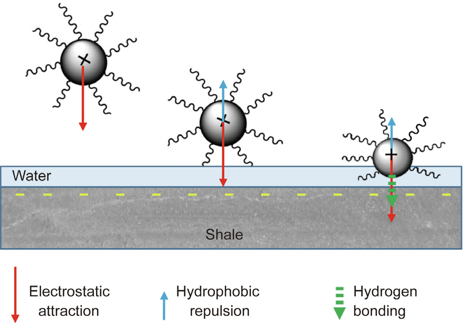
Fig. 12. The driving force of HNS adsorption onto the shale surface.
After adsorption, HNS balances part of the negative charge of the clay by means of electrostatic adsorption and reduces the repulsive hydration forces, thus reducing osmotic hydration. In addition, HNS changes the microstructure of the shale surface. A micro-nano hierarchical structure, which is similar to the surface structure of the lotus leaf, is formed on the shale surface, substantially increasing the contact angle of the shale surface. This results in a significant reduction in the free energy of the shale surface, which helps to inhibit the surface hydration of the shale. In addition, the decrease in capillary action and the plugging effect of HNS on the shale pores reduce the invasion of drilling fluid. These three aspects work together to effectively inhibit shale hydration and prevent a decrease in the strength of the shale during drilling, thereby helping to improve the wellbore stability.
《4. Conclusions》
4. Conclusions
In this work, a hydrophobic nanomaterial named HNS was synthesized to strengthen the wellbore wall. In aqueous media, the z-average particle size of HNS is 283 nm. The linear swelling test, hot-rolling recovery test, and compressive strength test of the shale all demonstrated that HNS has a good wellborestrengthening performance. Compared with KCl and polyether amine, HNS has a substantially better capability to inhibit the dispersion of water-sensitive shale. Furthermore, HNS can prevent the decrease of rock strength during drilling.
The main mechanism in strengthening the wellbore wall can be summarized as follows. Under electrostatic attraction, HNS balances part of the negative charge of the clay, thereby reducing repulsive hydration forces and osmotic hydration. The adsorption of HNS changes the microstructure of the shale surface and substantially increases the contact angle. This wettability alteration results in a significant decrease in the free energy of the shale surface, which helps to inhibit surface hydration. In addition, HNS can effectively plug the shale pores and form a seamless film, thus reducing the invasion of water and promoting wellbore stability.
《Acknowledgments》
Acknowledgments
Xianbin Huang, Jinsheng Sun, He Li, Ren Wang, Kaihe Lv, and Haichao Li are grateful to the National Natural Science Foundation of China (U1762212 and 51904329) and the Shandong Natural Science Foundation (ZR2019BEE002).
《Compliance with ethics guidelines》
Compliance with ethics guidelines
Xianbin Huang, Jinsheng Sun, He Li, Ren Wang, Kaihe Lv, and Haichao Li declare that they have no conflict of interest or financial conflicts to disclose.


 京公网安备 11010502051620号


