

《1. Introduction》
1. Introduction
Many countries have identified electric vehicles (EVs) as a national development strategy to push forward the energy transformation. EV deployment has been growing rapidly over the past 10 years, with the global stock of EVs passing 5 million in 2018. Under the new policies scenario, the global stock of EVs will exceed 130 million in 2030 [1]. With the increasing penetration rate of EVs, the charging of EVs should be dispatched well to avoid increased peak-to-valley load difference and losses, line overloads, and voltage-crossing limits in the distribution network [2]. Furthermore, as the EVs are off-road 90% of each day [3], and as EV batteries have the ability to quickly respond to system demand [4], the discharging of EVs is an important part of demand response to promote the optimal and secure operation of the power system [5]. Most of the current research on the demand response strategy of EVs [6–8] takes EV charging and discharging power as control variables, establishes relevant control models, and carries out optimization according to specific objectives, which include smoothing the renewable generation uncertainties and load fluctuation [6,9], reducing the cost or power loss [7,10,11], providing auxiliary services, and so on [2,12–15]. It is of great significance to assess the EV response capability as the fundamental link in developing a demand response strategy for EVs.
When there are a large number of EVs, the transportation network and power grid become deeply integrated in the geospatial dimension. The route choices of EV users, which are based on traffic guidance information within the transportation network, will determine the state of the EVs when they are plugged in. The EVs interact with the power grid by charging or discharging, considering their users’ travel demands and the operation of the power grid. It is clear that the EV response capability strongly depends on three critical factors: ① the state of the EV when it is plugged in— namely, the state of charge (SOC) and the plug-in time; ② user travel demand, which is reflected by the expected departure time and the required SOC; and ③ the reliability of the cyber system, which directly determines the traffic guidance information and the EV response to the power grid.
At present, research on the assessment of EV response capability can be divided into two main groups. The first group takes the SOC as the index. In Refs. [16–18], the EVs discharge when the SOC exceeds the given threshold, and the EV response capability is evaluated very quickly. However, user travel demand is ignored, and the SOC after discharging may be much less than what is required. The second group conducts an EV response capability assessment while considering user travel demand. Refs. [19,20] assume that an EV can only discharge when the SOC after discharging can meet the user’s demand; however, the user’s possibility for charging after discharging is ignored. Ref. [21] takes the difference between the duration of time the EV is plugged into the grid and the required charging time as the index for the discharging capability of an EV. However, it uses a relative index, which cannot reflect the absolute value of the response capability.
Three common methods are used to calculate an EV’s state when it is plugged in and its travel demand—namely, the fitting method, which is based on random variables [22,23]; the trip chain method [24,25]; and the method based on spatial dimension uncertainty [26–28]. The trip chain method can make use of the users’ travel destinations to build a space chain and calculate the travel time chain of the EVs in combination with the state of the transportation network to determine the travel time, mileage, and other variables of EVs. Compared with the other two methods, it can truly reflect the coupling relationship between the users’ travel time and distance, while considering the impact of the transportation network on users’ travel behavior. With the deep integration of the physical power network and the cyber system, the power distribution network becomes a typical cyber–physical system (CPS), which is referred to as the cyber–physical distribution network (CPDN) [29]. Furthermore, the operation and control of the smart distribution network strongly and deeply rely on the cyber system [30–34].
At present, the reliability assessment of the CPDN has been studied extensively, and this research can be divided into two main groups. The first group of research modifies the reliability model of the components in the physical power network based on an analysis of the interaction between the cyber system and the physical system; then, the consequences are analyzed and the reliability indices are calculated in a traditional way [35–37]. The second group of research focuses on specific functions that are strongly supported by the cyber system, establishes a mapping relation between cyber failure and the functions’ failure, and then calculates the reliability indices [29,38,39]. Although some work on the reliability assessment of the power system has taken EVs into account, such as that in Refs. [40,41], in determining the EV response capability, the cyber systems in both the transportation network and the power grid are considered to be completely reliable, and the reliability of the cyber systems in providing reliable traffic guidance information and in the bidirectional interaction between the power grid and the EVs is ignored.
To assess the EV response capability effectively, this paper proposes a novel assessment method that considers users’ travel demands and the reliability of the cyber systems integrated into both the power grid and the transportation network. First, a novel framework of an integrated cyber–power–transportation system is proposed, and a reliability model of the cyber system is provided. Next, a method is proposed to calculate the state of an EV when it is plugged in, while considering the reliability of traffic guidance information. Furthermore, the degree of relaxation in the EV charging demand is proposed to reflect user travel demand, based on which the EV response capability is assessed. Extensive test results on a cyber–power–transportation system that contains RBTS BUS6 and the Beijing transportation network are conducted to demonstrate the efficiency of the proposed method.
The rest of this paper is organized as follows. Section 2 introduces a framework of an integrated cyber–power–transportation system. A reliability model of the cyber system is presented in Section 3. Section 4 proposes a method to calculate the state of an EV when it is plugged in, considering the reliability of traffic guidance information. Section 5 further presents an EV response capability assessment method that considers EV users’ travel demands. Section 6 provides case study results and a related discussion, while Section 7 summarizes and concludes this work.
《2. Integrated cyber–power–transportation system》
2. Integrated cyber–power–transportation system
Fig. 1 shows the framework of the integrated cyber–power– transportation system. With the increasing number of EVs, the power grid and transportation network are integrated in the geospatial dimension. The operation and control of both the power grid and the transportation network strongly and deeply rely on cyber systems. For the power grid, the main station monitors and controls the power grid through a cyber system, and EV aggregators are adopted between the main station and the EVs to exchange information and manage the charging and discharging of the EVs. For the transportation network, the traffic control center collects real-time traffic data, and then generates and releases traffic guidance information, based on which travel route selections for the EVs are generated. The basic structure of the cyber systems in the power grid and transportation network are described below.
《Fig. 1》

Fig. 1. Framework of the integrated cyber–power–transportation system.
《2.1. Cyber system of the power grid》
2.1. Cyber system of the power grid
The cyber system of the power distribution network consists of a backbone layer and an access layer, as shown in Fig. 2. The backbone layer is the network between the main station and the substations and EV aggregators, based on the synchronous digital hierarchy (SDH). The access layer includes two parts: the network between the substations and the intelligent electronic devices (IEDs), which is based on an ethernet passive optical network (EPON) that includes optical line terminals (OLTs) and optical network units (ONUs); and the network between the EV aggregators and the EVs, which is based on EPON and Wi-Fi.
《Fig. 2》

Fig. 2. The cyber system of the power distribution network. (a) Backbone layer between the main station and substations and aggregators; (b) access layer between substations and IEDs; (c) access layer between EV aggregators and EVs.
《2.2. Cyber system of the transportation network》
2.2. Cyber system of the transportation network
The cyber system of the transportation network consists of a traffic control center, traffic substations, traffic informationcollecting devices, and so forth. Fig. 3 shows the basic structure, in which the backbone layer adopts SDHs to connect the traffic control center and traffic substations, while the access layer adopts EPON to connect the traffic substations and the detectors. The traffic control center collects traffic data, generates and releases traffic guidance information, and dispatches the transportation network. As the most widely used traffic information-collecting device, ring induction coil detectors are selected here.
《Fig. 3》
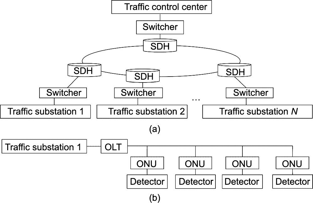
Fig. 3. Basic structure of the cyber system of the transportation network. (a) Backbone layer; (b) access layer.
Meanwhile, the traffic control center itself is a LAN-based system [42], including database servers, application servers, dispatchers, and so forth. The database server stores traffic data and traffic guidance information; then, the application server extracts information and transmits it to different release platforms. Fig. 4 shows the basic cyber structure of the traffic guidance information release, in which two database servers and two application servers are adopted to improve the reliability.
Consequently, the reliability of the cyber system in both Figs. 3 and 4 will affect the traffic guidance information and the release of traffic guidance information, respectively.
《Fig. 4》
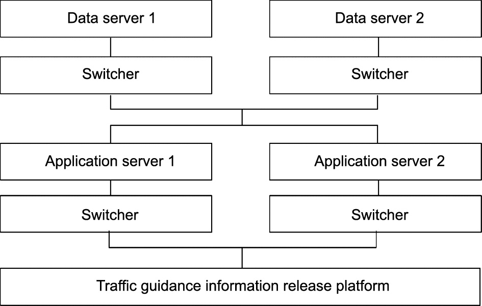
Fig. 4. Basic cyber structure of the traffic guidance information release.
《3. Reliability model of the cyber system》
3. Reliability model of the cyber system
《3.1. Reliability of physical components》
3.1. Reliability of physical components
A two-state Markov model is used to describe the failure and repair of physical components. Operating state duration (the time to failure, TTF) and outage state duration (the time to repair, TTR) can be further calculated as shown in Eqs. (1) and (2):

where  and
and  are the failure rate and repair rate, and u1 and u2 are random numbers that are subject to the uniform distribution in [0, 1].
《3.2. Reliability of information transmission》
3.2. Reliability of information transmission
Information, such as measurement data and control signals, is transmitted through the communication network. The connectivity and performance of the communication network determine the reliability of the information transmission.
3.2.1. Connectivity of the communication network
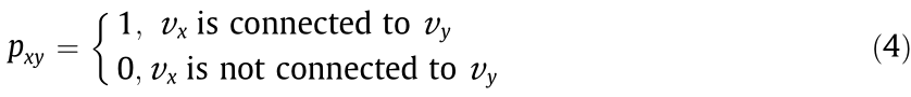
The communication network can be represented by an undirected connected graph, set as G = (V, E). All components are regarded as nodes (including the communication lines), which are represented by V = {υ1, υ2, ..., υn}, and the connection relationships between nodes are regarded as edges, which are denoted by E = {e1, e2, ..., en}. An adjacency matrix A(G) =  can be defined as follows:
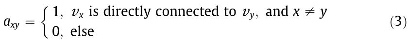
where G is an undirected connected graph representing the communication network; V is the set of nodes υ; E is the set of edges e; x and y are the numbers of the corresponding nodes.
The reachability matrix 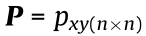 is used to describe the connection relationship pxy between nodes υx and υy, which can be defined as follows:
The k-step reachability matrix is calculated as follows:

Then the non-zero element in M is set to 1 to obtain the reachability matrix P, and the network connectivity can be determined.
3.2.2. Performance of the communication network
The performance of the communication network can be evaluated in terms of information delay, packet loss, bit error, and so on. After the end-to-end information transmission is completed, the receiving end will return a response packet to confirm whether the information has been reliably transmitted. Data retransmission can effectively avoid the impact of packet loss and bit error. Therefore, the transmission delay is considered and the uncertainties of the transmission delay are modeled as a normal distribution [43]. The transmission will be unsuccessful if the delay exceeds the given threshold.
《4. State of plugged-in EV considering the reliability of traffic guidance information》
4. State of plugged-in EV considering the reliability of traffic guidance information
《4.1. Route selection considering the reliability of traffic guidance information》
4.1. Route selection considering the reliability of traffic guidance information
Since travel time is the most important factor for users to select routes, it is assumed that users select the route with the shortest travel time, according to Eqs. (6)–(8):
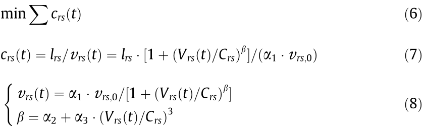
where r, s are the nodes at the two ends of the road respectively; crs(t) is the time impedance—namely, the required time to pass road (r, s); Vrs(t) is the traffic flow collected by the ring induction coil detectors;  and υrs(t) are the length and traffic speed of road (r, s); υrs,0 and Crs are the designed traffic speed and traffic capacity of road (r, s), respectively; and α1, α2, and α3 are the given model parameters.
Considering the reliability of the cyber system in Fig. 3, failure of cyber components and information transmission may result in detector data loss, and the average values of the data in adjacent time periods will be used to fill in for the missing data [44]. Vrs(t) and crs(t) will be updated as follows:

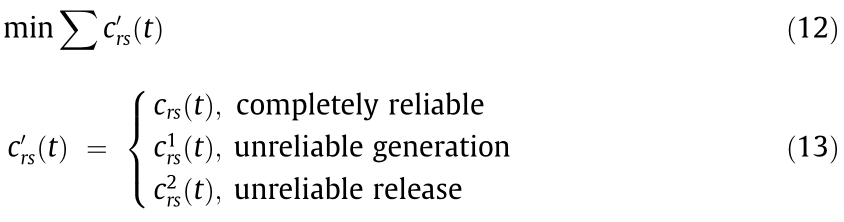
Considering the reliability of the cyber system in Fig. 4, the release of traffic guidance information may fail, and EV users will select travel routes based on their perceived impedance  , which is shown as follows:

where  is the deviation of the time impedance, which follows the Gumbel distribution with a mean value of 0.
In summary, the routes will be selected based on Eqs. (12) and (13), considering the reliability of the traffic guidance information.
《4.2. State of EV when plugged in》
4.2. State of EV when plugged in
A trip chain is used to simulate an EV user’s daily traveling. As shown in Fig. 5, the trip chain of user i consists of a space chain and a time chain:
(1) Space chain: The node represents the user’s travel destination, the line between two nodes represents the user’s driving path, and the mileage of the jth trip is mi,j.
(2) Time chain: The node represents the time node,  and
and  represent the starting time and ending time of the daily trip, respectively, and
 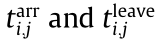 represent the arriving time and leaving time at the jth destination, respectively. The dashed line and the corresponding
  represent the travel time between two destinations. The solid line and the corresponding
  represent the stay time at destination j.
The method of calculating variables in the trip chain is introduced further below.
《Fig. 5》
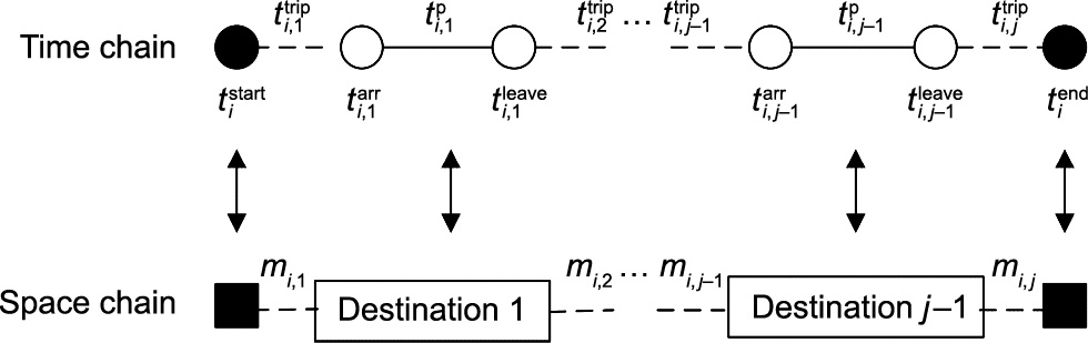
Fig. 5. The trip chain.
4.2.1. Space chain
(1) EV daily travel schedule. An activity sampling-based travel schedule model [45] is used to generate the space chain. The residential area is the starting and ending area of the daily travel, and destinations include the working area, shopping mall, hospital, residential area (i.e., returning home partway through the day), and scenic spot. The EV daily travel schedule can be sampled based on the statistical probabilities of the variable activities. If the destinations include the working area, then the working area should be placed in the first position. If the destinations include the residential area (i.e., returning home partway through the day), then it should be placed in a random position, excluding the beginning and end of all destinations. Other destinations are randomly scheduled.
(2) Mileage mi,j considering the reliability of traffic guidance information. As introduced in Section 4.1, users select a route according to Eqs. (12) and (13), and then mi,j and the related power consumption  can be calculated as follows:

where S is the set of all roads of the selected route; wrs(t) is the power consumption of the EV for 1 km, calculated by the method provided in Ref. [46]; and B is the capacity of the EV battery.
4.2.2. Time chain
(1) The starting time of the daily trip. The  follows a normal distribution [47]:

where μ1 = 7.8 and σ1 = 1.5.
(2) The travel time between two destinations. The  can be calculated as follows:

(3) The leaving time at the jth destination. If the trip starts from the working area, then  is the departure time from the working area,
  , which follows a normal distribution [47]:

where μ2 = 17.5 and σ2 = 0.5.
If the trip starts in other areas, then  can be calculated as follows:
where  is the stay time at a non-work destination j, μ3 = 1.5, and σ3 = 0.5.
4.2.3. Fast charging analysis
Users will change their route and select the nearest EV charging station for fast charging if the SOC meets the following condition:

Existing fast chargers at EV charging stations generally charge the SOC to about 80% at high power, and then slowly charge it at low power. Therefore, the user is considered to leave the charging station after the SOC reaches 80%. The time for fast charging can be calculated as follows:

where  is the power consumption from the current destination to the charging station, and Pchf is the rated fast charging power.
《4.3. Procedure for calculating the state of an EV when plugged in》
4.3. Procedure for calculating the state of an EV when plugged in
Fig. 6 outlines the procedure for calculating the state of an EV when it is plugged in.
《Fig. 6》

Fig. 6. Procedure for calculating the state of an EV when it is plugged in.
《5. EV response capability assessment considering user demand》
5. EV response capability assessment considering user demand
《5.1. EV charging strategy》
5.1. EV charging strategy
EVs spend most of the time parked in residential and working areas, with a relatively short time spent in other areas. In the main distribution station–aggregator hierarchical control structure, when EV i is plugged into the grid in a residential or working area, the following charging optimization will be performed by the aggregator to minimize the total load variance of the system.
where Pch,i(t) is the charging power of the ith EV at time t; Pi–1(t) is the total load, including the previous 1 to i – 1 EVs at time t; P is the
average load within the optimization period T;  i is the SOC demand; and Pchr,i is the rated charging power. DPlug,i(t) = 1 if the EV is plugged in; otherwise, DPlug,i(t) = 0.
The variables in Eqs. (23)–(27) can be calculated as follows:
where  represents the fast charging power at the charging station; sj,j+1 represents the state of communication between the aggregator with the (j + 1)th EV and the aggregator with the jth EV; sj,j+1 = 1 means that the communication is successful; and sj,j+1 = 0 means that the communication is unsuccessful.
《5.2. EV response capability based on the degree of relaxation in the EV charging demand》
5.2. EV response capability based on the degree of relaxation in the EV charging demand
The degree of relaxation in the EV charging demand is proposed as follows:

where tleave,i –t represents the remaining rechargeable time of the ith EV at moment t; and  represents the remaining required charging time to meet the ith EV travel demand at moment t. Therefore, Li(t) represents the urgency of the ith EV charging at moment t, where the smaller Li(t) is, the stronger the EV charging demand is and the weaker the response capability is.
According to Li(t), EVs can be classified as follows:
(1) Li(t) < 0: User demand cannot be satisfied even if EV is continuous charged.
(2)  : If EV is charged continuously from now until the departure time; user demand can be satisfied, but the charging process must be uninterrupted.
(3)  : The EV charging process can be interrupted, but if the EV discharges, user demand cannot be satisfied.
(4)  : The charging process can be interrupted and the EV can discharge, where
  is the unit time for optimal scheduling and Pdis,i is the rated discharging power.
To reduce damage to the EV battery, the EV SOC should not be less than 20%, and the EV that can discharge at time t should satisfy Eq. (34):
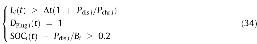
Then, the EV response capability  considering the user demand at time t is

To describe the relationship between the EV SOC when the user leaves and the user’s travel demand, EV user satisfaction is defined as follows:

where N is the total number of EVs, and Ns is the number of EVs with enough SOC that can meet the user travel demand after leaving.
《6. Case study》
6. Case study
As shown in Fig. 7, a system containing RBTS BUS6 [48] (upper layer) and the Beijing transportation network (lower layer) was taken as a study case. The transportation network formed by the expressway (red line) and the main road (blue line) within the fifth ring road in Beijing is equivalent to a 25 km × 25 km connected graph, in which the road network node is placed on a corresponding grid node with a unit length of 1 km. There are 2370 EVs, given that the penetration rate of EVs is 50% and the ratio of private vehicles to residential users is 1.86 [47]. The load points in RBTS BUS6 corresponding to the Beijing transportation network are given in Table 1. The reliability parameters of cyber components and detailed information on RUTS BUS6 and the Beijing transportation network can be found in Refs. [48–51]. The simulations were realized through the MATLAB platform, with a focus on day-ahead optimization scenarios with 1 h increments.
《Fig. 7》
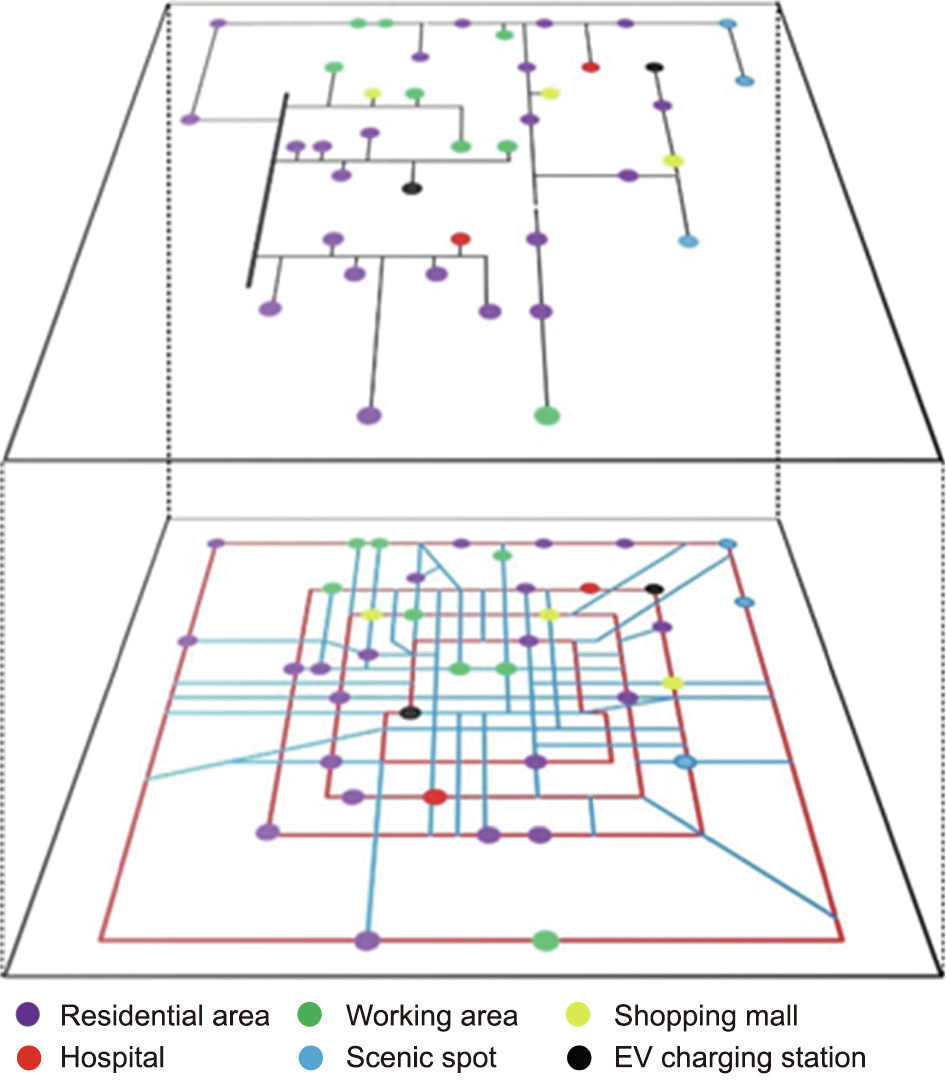
Fig. 7. Power distribution network–transportation system of the study case.
《Table 1 》
Table 1 Load points in RBTS BUS6 corresponding to the Beijing transportation network.
《6.1. Assessment of EV response capability》
6.1. Assessment of EV response capability
Case 1: EVs can discharge if the proposed Eq. (34) is satisfied.
Case 2: EVs can discharge if the SOC is higher than a certain threshold, which is set at 80%, 70%, 60%, and 50%, respectively [16].
Case 3: EVs can discharge only when the SOC after discharging is higher than the users’ demand [20].
The EV response capability for different cases in the residential area is given in Fig. 8. Apparent differences can be found between the cases. The response capability in Case 3 is significantly lower than that in the other two cases, because the SOC of most of the EVs that just came back cannot meet the users’ subsequent travel demands. Case 1 has a higher response capability than Case 2 from 11:00 on one day to 2:00 the next day, using a 24 h clock. After 2:00, the response capability of Case 1 decreases and is lower than that of Case 2, because the users’ demands should always be met in Case 1, and discharging may prevent the users’ demands from being met due to the approaching departure time.
《Fig. 8》

Fig. 8. EV response capability in the residential area.
Fig. 9 depicts EV users’ satisfaction in the residential area. User satisfaction in Case 1 and Case 3 is always 1. In Case 2, user satisfaction remains close to 1 from 12:00 to 24:00, but decreases significantly from 1:00 to 11:00; furthermore, the lower the SOC threshold is, the lower the satisfaction is.
《Fig. 9》

Fig. 9. EV user’s satisfaction in the residential area.
As shown in Figs. 10 and 11, the EV response capability and EV user satisfaction in different cases in the working area are similar to those in the residential area. It is worth noting that the response capability in Case 2 is almost the same with thresholds of 50% and 60%. This is because the number of EVs with a SOC of 50%–60% in the working area is almost 0, as shown in Fig. 12.
《Fig. 10》
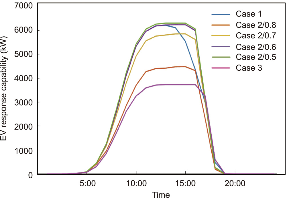
Fig. 10. EV response capability in the working area.
《Fig. 11》

Fig. 11. EV user’s satisfaction in the working area.
《Fig. 12》
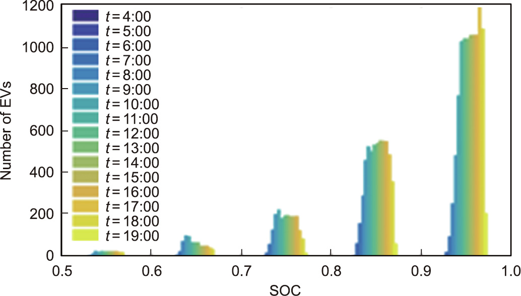
Fig. 12. EV SOC distribution in the working area.
It can be seen that the EV response capability can be maximized to meet the users’ travel demand by means of the proposed method.
《6.2. Impact of traffic guidance information on EV trips》
6.2. Impact of traffic guidance information on EV trips
Table 2 provides the simulation result for EV trips, considering the reliability of traffic guidance information (i.e., its generation) and the reliability of its release. When the traffic guidance information is completely reliable, EV users can accurately identify the traffic network state and choose the routes that take the shortest time. However, mileage and power consumption may increase. In contrast, unreliable traffic guidance information or the unreliable release of information will cause an obvious increase in the average daily travel time, as well as delays in arriving at the working area and returning to the residential area. Figs. 13 and 14 provide the probability distribution of the EVs’ arrival time at the working area and return time at the residential area. It can be found that the probability distributions of time corresponding to unreliable traffic guidance information and the unreliable release of such information are relatively close and significantly lag behind the probability distribution with completely reliable traffic guidance information. With the unreliable release of traffic guidance information, users who select routes based on their own perceived impedance within the traffic network may select routes with the shortest mileage instead of the shortest time, so the users’ travel time becomes longer, while the parameters related to the driving mileage, such as the average daily mileage, average daily power consumption, proportion of fast charging, and average fast charging energy, become smaller.
《Table 2 》
Table 2 Impact of traffic guidance information on EV trips.

《Fig. 13》
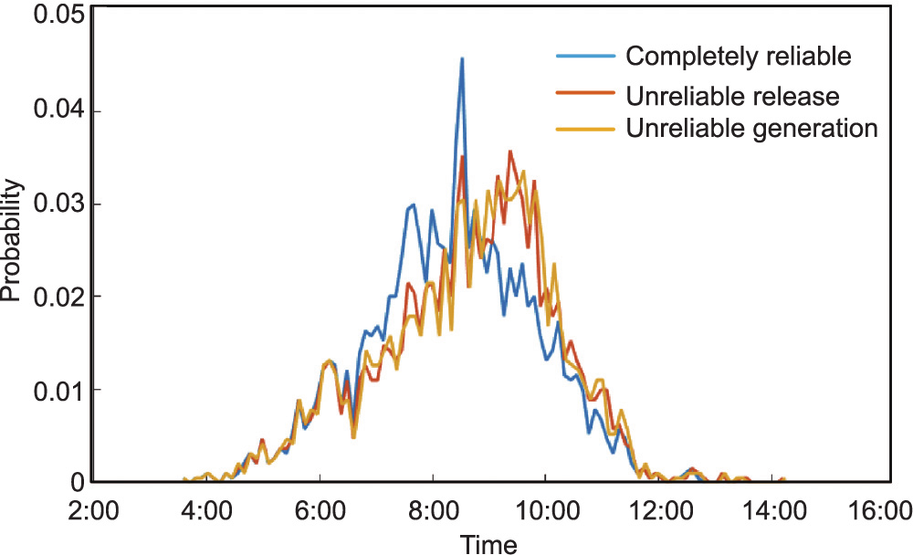
Fig. 13. Probability distribution of EVs’ arrival time at the working area.
《Fig. 14》
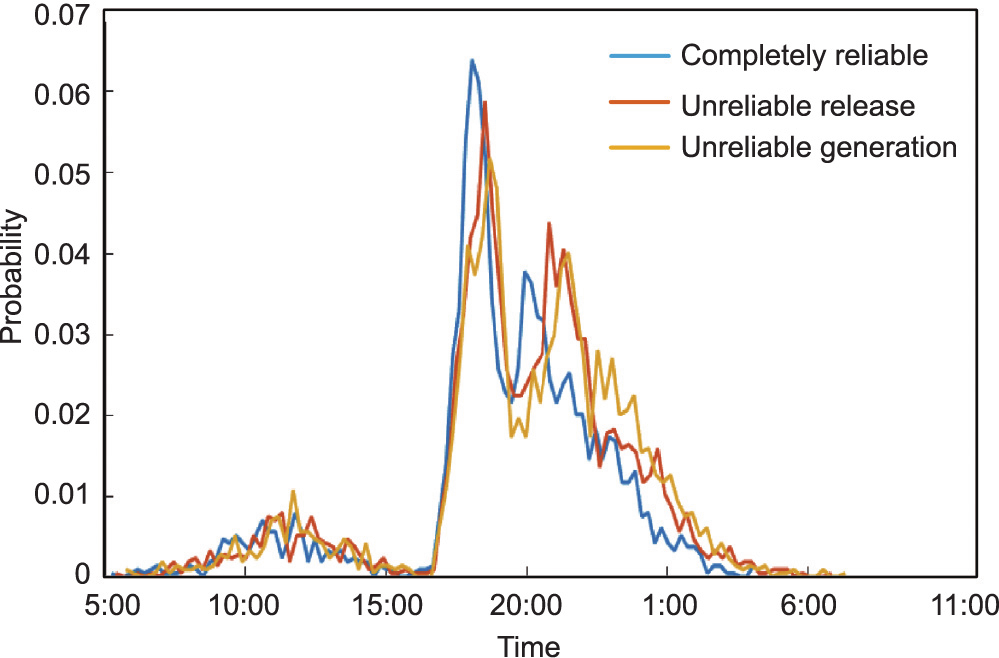
Fig. 14. Probability distribution of EVs’ return time at the residential area.
《6.3. Impact of the reliability of cyber systems on EV response capability》
6.3. Impact of the reliability of cyber systems on EV response capability
Case 1: The cyber systems are completely reliable.
Case 2: The cyber system of the power distribution network is completely reliable, and the reliability of the transportation cyber system is considered.
Case 3: The transportation cyber system is completely reliable, and the reliability of the cyber system of the power distribution network is considered.
Case 4: The reliability of the cyber systems of both the transportation network and the power distribution network are considered.
Fig. 15 shows the EV response capability of different cases at the working area and residential area. It is clear that the reliability of the cyber system has a great impact on the EV response capability, which is lower in Cases 2–4 than in Case 1. The reliability of the transportation cyber system mainly affects the EV response capability during the centralized plug-in time of the EVs, while the reliability of the cyber system of the power distribution network affects the EV response capability all the time and to a greater extent. This is because multiple real-time communications and links are required in the control of EV charging/discharging, which raises the probability of unreliable information transmission, and results in part of the EVs being in an uncontrollable state and a significant decrease in the system response capability.
《Fig. 15》
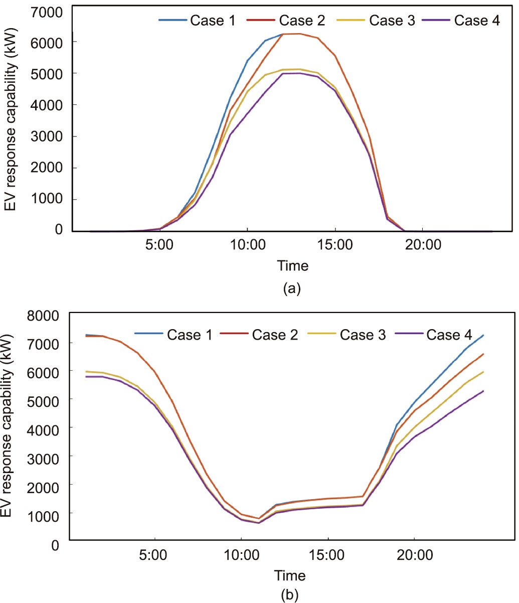
Fig. 15. EV response capability of different cases at (a) the working area and (b) the residential area.
《7. Conclusions》
7. Conclusions
This paper proposes an EV response capability assessment method that considers EV users’ travel demand and the reliability of the cyber systems integrated into both the power grid and the transportation network. The simulation results of the improved system, which includes the Beijing transportation network and RBTS BUS6, show that the proposed method, based on the degree of relaxation in the EV charging demand, can maximize the EV response capability while always satisfying the users’ travel demand. Unreliable traffic guidance information or the unreliable release of such information will affect EV trips and eventually delay the EV plug-in time. The reliability of the cyber system has a great impact on the EV response capability, with the cyber system of the power distribution network having a greater impact than that of the transportation cyber system.
The proposed method not only assesses the EV response capability more accurately and effectively than other current methods, but also supports the joint planning and optimal operation of cyber–power–transportation systems. Furthermore, the impacts of the transportation cyber system are only considered from the aspect of traffic guidance information in this paper. The function of the transportation cyber system on transportation system dispatching will be considered in our future work. In addition, the dynamic thermal rating (DTR) system holds strong potential for upgrading the power grid. Given the many sensors and aggregators in the DTR, extensive communication among them cannot be ignored. Therefore, in order to deal with the line-overloading problem that may be caused by plug-in EVs, the reliability of the DTR cyber system will be considered in our future work. Given the increasing risk of cyberattacks, which may lead to transmission interruptions, transmission delays, information tampering, and other failures in cyber systems, the effects of cyberattacks on EV response capability in CPDN cannot be ignored. The first two effects have been discussed in this paper; information tampering will also be studied in the future.
《Acknowledgments》
Acknowledgments
This work was supported by the National Key Research and Development Program of China (2017YFB0903000), and the Basic Theories and Methods of Analysis and Control of the Cyber Physical System for Power Grid.
《Compliance with ethics guidelines》
Compliance with ethics guidelines
Yanli Liu, Ke Liu, and Xu Sun declare that they have no conflict of interest or financial conflicts to disclose.


 京公网安备 11010502051620号


