

《1. Introduction》
1. Introduction
Laser powder bed fusion (LPBF) is a typical metal additive manufacturing (AM) or three-dimensional printing (3DP) process, which is performed based on layer-by-layer powder spreading and subsequent laser melting and consolidation [1]. During the LPBF process, a layer of metal powder on the building substrate is entirely melted by a high-energy laser beam in a protective atmosphere along the path set by a computer. The melt is cooled and solidified quickly to form a fully dense two-dimensional (2D) layer after the laser beam moves away. By repeating this procedure, components with any complex geometry can be directly processed by LPBF [2–4]. LPBF technology has developed rapidly in recent years, showing considerable application potential in the aerospace [5,6], biomedical [7], and automobile industries [8]. Due to its significant advantage in fabricating complex parts, increasing attention has been spent on creating customized parts or novel mechanisms by means of LPBF, such as non-assembly mechanisms and compliant mechanisms [9].
The compliant mechanism, which was first proposed at Purdue University in the late 1980s, was a mechanical device used to transfer/transform motion, force, or energy [10]. In general, compliant mechanisms can exhibit a large strain capacity due to low stiffness [11]. Bending-dominated joints are typically applied in compliant mechanisms, resulting in a stress–strain response with a long and flat plateau [12]. Therefore, compliant mechanisms have significant potential for energy-absorption applications, among which cellular contact-aided compliant mechanisms are regarded as good examples [13]. The compression-induced twisting (CIT)- compliant mechanism is a unique compliant mechanism that exhibits a twisting behavior under uniaxial compression. As a programmable twisting angle per unit of axial strain can be obtained for the CIT-compliant mechanism through innovative design, the mechanism demonstrates potential application opportunities in aerospace engineering, smart actuators, propellers, smart flexible microelectronics, and biomechanical devices. Inspired by 2D chiral honeycombs, Frenzel et al. [14] proposed a novel threedimensional (3D) metamaterial with the CIT effect, fabricated by means of the 3D laser microprinting of polymer materials. It was found that the twist angle per unit of axial strain of this 3D metamaterial could reach 2°∙%–1 , which was attributed to advanced mechanical designs using coordinate transformations. Wu et al. [15] designed a novel tetrachiral architected cylindrical tube based on the chiral cell and prepared the samples by means of selective laser sintering (SLS). They found that a linear relationship existed between the rotation angle and compressive force. Zhong et al. [16] also proposed a novel 3D mechanical metamaterial with the CIT effect and discussed the effects of the inclined angle of the cell and the transverse and longitudinal cell numbers on the compression–torsion properties of the 3D compression–torsion metamaterial. The twisting angle per unit of axial strain of a metamaterial fabricated by acrylonitrile butadiene styrene (ABS) plastic reached 16.2°∙%–1 , showing a significant CIT effect. Shaw et al. [17]designed a kind of directionally compliant metamaterial based on freedom and constraint topologies (FACT) and fabricated it using two-photon lithography. A fully linear behavior between the rotation angle and compression strain was observed in experiments. The abovementioned CIT-compliant mechanisms exhibit an extensive strain capability under uniaxial compression, thereby demonstrating potential for energy-absorption structures. However, previous investigations have mainly focused on the design of geometric configurations, and polymer materials have typically been used to prepare the investigated samples. Few studies have been conducted on the formation process of metal CIT-compliant mechanisms or on the effect of the formation process on the mechanical properties or energy-absorption behavior. Compared with polymer materials, metal materials have better mechanical properties and broader applications in various industries. Hence, it is valuable to carry out investigations on the formation process and mechanical properties of metal-based CIT-compliant mechanisms. For the LPBF of metals, metallurgical defects (e.g., low surface quality and porosity [18–20]) are always significant challenges to be solved. Thus, the roles of the laser processing parameters in the formation quality and mechanical properties of metal-based CIT-compliant mechanisms fabricated by LPBF must be clarified.
In this research, a novel CIT-compliant mechanism based on the FACT method was designed and then fabricated by LPBF using AlSi10Mg powder under different laser powers. The effects of the laser processing parameters on the densification level, dimension accuracy, surface roughness, mechanical deformation behavior, and energy-absorption capacity of LPBF-fabricated CIT-compliant mechanisms were studied. Numerical simulations and compression experiments were further performed to reveal the stress distribution and underlying deformation mechanisms.
《2. Experimental and modeling methods》
2. Experimental and modeling methods
《2.1. Geometric design》
2.1. Geometric design
Based on the FACT method, a novel CIT-compliant mechanism was designed, as shown in Fig. 1. During the design process, multi-axis parallel flexure systems were created based on the constraint-based design principle and the mathematics of screw theory and projective geometry [21]. Fig. 1(a) shows a hyperboloid proposed by Hopkins and Culpepper [22], which can twist under uniaxial compression along the screw line. According to Hopkins and Culpepper’s work [23], the relationship between compression displacement and twisting angle is described by the following equation:

where p is the pitch of the twist, d is the shortest distance between the screw and constraint lines, and θ is the skew angle between the screw and constraint lines (Fig. 1(b)). The twisting behavior of hyperboloid structures depends on the inclined angle θ of the strut and the radius R of the loop. In the current work, the designed CIT-compliant mechanism consists of two hyperboloids, corresponding to hyperboloid A with a top circle of R1 = r and hyperboloid B with a top circle of  where r is the circumradius of the regular hexagon showed in Fig. 1(c). As shown in Fig. 1(c), the inclined struts connected with the hexagonal vertices and midpoints are named the V–V struts and M?M struts, respectively. According to Eq. (1), the pitch (mm∙rad–1 ) of hyperboloid A is
  and that of hyperboloid B is
  , where h is the overall height of the CIT-compliant mechanism. The corresponding computer-aided design (CAD) model is given in Fig. 1(d), in which the side of the regular hexagon is marked as
  and the diameter of the struts is marked as Φ.
《Fig. 1》
Fig. 1. Design procedure of the CIT-compliant mechanism. (a) A hyperboloid structure; (b) two different hyperboloid structures, for which the radiuses of their loops are r and  , respectively; (c) the designed CIT-compliant mechanism in our work, which consists of two hyperboloids; (d) the corresponding computer-aided design model.
《2.2. LPBF processing of CIT-compliant mechanisms》
2.2. LPBF processing of CIT-compliant mechanisms
According to the abovementioned model of the CIT-compliant mechanism, h, , and Φ were determined to be 21, 10, and 1 mm, respectively. The CIT-compliant mechanisms were then fabricated by means of LPBF, using an LPBF system self-developed at Nanjing University of Aeronautics and Astronautics (NUAA). AlSi10Mg powder with a mean particle size of 23 μm was used as the raw material. The morphology of the powder and the particle-size distribution are shown in Fig. 2.
《Fig. 2》

Fig. 2. (a) Morphology and (b) particle-size distribution of the AlSi10Mg powder applied in our work.
A series of critical operation procedures were involved in the LPBF process. First, an aluminum (Al) substrate was fixed on the building cylinder, and a flexible scraper blade was installed on the automatic powder-spreading device. The AlSi10Mg powder was then rapidly poured into the powder cylinder and the building chamber was sealed. The inert argon (Ar) protection system was opened to decrease the oxygen (O2) content to below 20 parts per million (ppm). Next, the powder-spreading device and laser beam were activated to start LPBF production. As the laser beam scanned the powder bed based on the CAD model data, a longexposure photograph of the interaction between the laser beam and the powder was obtained and is displayed in Fig. 3(a), showing a steady forming process. The final as-built samples are shown in Fig. 3(b). In order to investigate the effect of the LPBF printing parameters on the formability and mechanical properties of the CIT-compliant mechanism, four different laser power parameters were used in this study, including 375, 400, 425, and 450 W. The other processing parameters were set as follows: scan speed υ of 3000 mm∙s–1 , powder layer thickness t of 30 μm, hatch spacing s of 50 μm, and beam compensation  of 60 μm.
《Fig. 3》

Fig. 3. Photographs of (a) the LPBF manufacturing process and (b) as-printed samples of the CIT-compliant mechanism.
《2.3. Compressive testing》
2.3. Compressive testing
Compression experiments were carried out at room temperature using a CMT5205 testing machine (MTS Systems Corporation, USA) with a capacity of 100 kN in a displacement control mode. In order to reduce the effect of friction during the compression test, graphite was used to lubricate the contact surface between the sample and the fixed plate. In the compression experiment, the displacement rate was set at 2 mm∙min–1 by controlling the crosshead velocity. The termination condition of the compression test was set at a displacement of 10 mm, as shown in Fig. 4(a).
《Fig. 4》

Fig. 4. Schematics of (a) the compression experiment set and (b) the indirect metrical method of the rotation angle.
An indirect method for measuring the rotation angle was adopted, as shown in Fig. 4(b). For the CIT-compliant mechanism, the circumcircles of the top and bottom hexagons were concentric. As the crosshead moved down, the top hexagon remained stationary due to friction, while the bottom hexagon tended to rotate due to the lubrication of the graphite. The following equation was used to calculate the rotation angle ω based on Euclidean geometry.
where α is the horizontal distance between the top and bottom hexagonal vertices, and β is the horizontal distance between two adjacent fixed vertices on the top hexagon, as shown in Fig. 4(b).
The special energy absorption (SEA), which considers the effect of structural mass, has been widely applied to determine the energy-absorption capacity of a structure. The equation for SEA is mathematically given as follows:

where F(x) is the instantaneous load during the compression process, L is the effective deformation of the structure, and m is the structural mass.
《2.4. Microstructure characterization and accuracy measurement》
2.4. Microstructure characterization and accuracy measurement
After LPBF processing, the diameters of inclined struts were measured with a Vernier caliper to evaluate the formation accuracy of the LPBF-processed components; average values were obtained based on at least six measurements. The Archimedes principle was used to measure the relative density of the samples. One inclined strut was taken from the sample, and then the strut’s roughness was measured by means of a roughness tester (SJ-210, Mitutoyo, Japan). After the struts were ground and polished following standard metallographic procedures, the internal microstructures of the inclined struts were observed with an optical microscope (BX53M, Optec, China). A scanning electron microscope (LYRA3 GMU, TESCAN, Czech Republic) was used to observe the fracture surface morphology of samples that had been fabricated under different laser printing parameters.
《2.5. Numerical simulation》
2.5. Numerical simulation
In order to gain more insight into the deformation mechanism of the CIT-compliant mechanism under uniaxial compression, corresponding simulation work was performed using finite-element analysis (FEA) software. The Ansys workbench was used to pretreat the model, and two rigid rectangular plates were placed at the two sides of the CIT-compliant mechanism. The size of the model used in the FEA was the same as the design value. The unit sizes of the rigid plates and the CIT-compliant mechanism model were set at 0.5 and 0.2 mm, respectively. The total number of units of the two plates was 32 319, and the total number of units of the CIT-compliant mechanism was 1 557 708. The compression speed of the moving plate was set at 10 m∙s–1 , and the bottom plate was fixed. The material properties of the Al alloy were set at a density of 2.65 g∙mm–3 , a Poisson’s ratio of 0.33, and a Young’s modulus of 73.3 GPa.
《3. Results and discussion》
3. Results and discussion
《3.1. Densification behavior》
3.1. Densification behavior
Fig. 5 gives the relative densities and absolute masses of the LPBF-fabricated CIT-compliant mechanisms at different laser powers. The relative densities of the samples decreased slightly with the increase of laser power, with the highest relative density being 97.8%. The difference between the highest and the lowest densities was only 0.4%. Within the range of laser powers from 375 to 450W, changes in the overall relative densities of the LPBF-fabricated CITcompliant mechanisms with laser power were not apparent, and the relative density of samples remained at around 98%. On the other hand, we found that the absolute mass of the LPBFfabricated CIT-compliant mechanisms clearly increased as the applied laser power increased (Fig. 5). The mass fluctuation can be attributed to the formation of slag in the overhanging structure. That is, due to the gravity effect of the melt and to the thermal capillary effect [24], many metallurgical pores and partly melted (or even unmelted) powder particles remained under the solidified horizontal struts, resulting in the formation of overhanging slag. Typically, the overhanging slag was observed at the bottom of the horizontal struts. Normally, more of the liquid phase was present when a relatively higher laser energy input was applied, which intensified the gravity effect and the thermal capillary effect, causing severe formation of overhanging slag [25]. As a result, the absolute mass of the LPBF-fabricated CIT-compliant mechanism clearly increased. A high porosity rate caused by the overhanging slag further deteriorated the overall densification degree of the LPBF-fabricated CIT-compliant mechanism.
《Fig. 5》

Fig. 5. Relative densities and absolute masses of LPBF-processed samples using different processing parameters. Photographs of the laser-printed CIT-compliant mechanism and the formation of overhanging slag in the horizontal strut are inserted.
In addition to being present in the horizontal struts, overhanging slag formed in the inclined struts. Fig. 6 exhibits cross-sectional optical images of the inclined struts fabricated at different laser powers. Some residual metallurgical pores were observed near the overhanging surface of the inclined struts. When the laser beam scanned the powder bed without the support of the underlying solid materials, the molten material flowed down into the powder bed under the effect of gravity. The gas in the powder bed was trapped by the solidified material, resulting in the formation of residual pores. It can be observed that the residual pores in the printed inclined struts gradually disappeared with the increase of laser power. At a relatively higher laser power, a larger temperature gradient tended to form within the molten pool, resulting in an enhanced convection flow and the attendant elimination of dissolved gas and porosity.
《Fig. 6》

Fig. 6. Optical micrographs showing the internal densification levels of inclined struts in (a) samples respectively manufactured with processing parameters of (b) 375 W, (c) 400 W, (d) 425 W, and (e) 450 W reveal the influence of slag on the overhanging surface on the residual porosity and densification rate of the laserprinted CIT mechanism.
《3.2. Dimension accuracy and surface roughness》
3.2. Dimension accuracy and surface roughness
In order to better evaluate the formation quality of the LPBFfabricated CIT-compliant mechanism, we further measured the diameter and roughness value of the inclined strut within the LPBF-fabricated CIT-compliant mechanism. The diameter Φ of the inclined strut was lower than the designed value at a relatively low laser power (e.g., 375 W). In comparison, Φ was larger than the designed value as the laser power increased to 425 W, as shown in Fig. 7(a). The actual diameters of the inclined struts fabricated under different laser powers fluctuated around the designed value, and the formation error of the inclined struts was found to be ±1.5%, showing acceptable dimensional accuracy. The accuracy was attributed to the tailored beam compensation, which effectively weakened the effect of the adhered powder particles on the dimensional accuracy.
As shown in Fig. 7(b), an increase of laser power contributed to a decreasing surface roughness value. The corresponding surface morphologies of the inclined struts fabricated at different laser powers are shown in Figs. 8(a)–(d). The influence of laser power on the surface morphology of the inclined strut is schematically presented in Fig. 8(e). When a low laser power was applied, the temperature of the melt was relatively low, resulting in high surface tension and viscosity of the melt [26]. Driven by the high surface tension, the melt tended to form individual coarsened spheres with diameters greater than 100 μm (marked in Figs. 8(a)–(c)), which is the so-called ‘‘balling effect.” When high laser power was applied, the surface tension and viscosity of the melt were reduced, due to the high temperature of the melt, so less of the ‘‘balling effect” was observed on the surface of the inclined strut (Fig. 8(d)). With an increase of laser energy, the recoil pressure increased and more particles were pushed away from the melt [27], resulting in fewer bonded particles on the surface of the inclined strut. Those two factors contributed to the enhanced surface quality of the inclined strut fabricated under high laser energy. Similar results have also been reported in the literature [28].
《Fig. 7》

Fig. 7. (a) Dimensional accuracy and (b) average surface roughness (Ra) of laser-printed CIT-compliant mechanisms at different processing parameters.
《Fig. 8》

Fig. 8. Surface morphologies of the inclined struts of the samples manufactured with different laser powers: (a) 375 W, (b) 400 W, (c) 425 W, and (d) 450 W. (e) Schematics of the effect of laser power on the formation behavior and surface roughness of the inclined strut.
《3.3. Mechanical deformation behavior》
3.3. Mechanical deformation behavior
In order to investigate the compressive deformation behavior of the LPBF-fabricated CIT-compliant mechanism and the influence of laser power on the mechanical response, uniaxial compression tests were performed. Fig. 9(a) displays photographs of the mechanical deformation behavior of the CIT-compliant mechanism (fabricated at P = 450 W) with displacement. The load–displacement (L–D) and specific energy absorption–displacement (E–D) curves of the LPBF-fabricated CIT-compliant mechanisms obtained under different laser powers are shown in Figs. 9(b) and (c), respectively. According to the observed deformation features and L–D curves, four distinguishable deformation stages were determined: the elastic stage, heterogeneous plastic deformation stage, strength-destroying stage, and deformation-destroying (or instable deformation) stage. During the compression test, the base of the CIT-compliant mechanism started to rotate with an increasing displacement, while the top side remained stationary due to friction. Taking the sample fabricated at P = 450 W as an example, the L–D curve exhibited a linear relationship due to elastic buckling of the inclined struts before the displacement reached about 1.5 mm. As the displacement increased, heterogeneous plastic deformation occurred, and apparent plastic buckling of the inclined strut was observed, as shown in Fig. 9(a). At a displacement of about 2.6 mm, the suffered load reached a maximum of about 0.2 kN and then declined slowly, together with a relatively rapid increase of displacement, exhibiting a quasi-yield period. It should be noted that the yield displacement was about 2.3 mm for the sample fabricated at P = 375 W. At an accumulated displacement of about 4.9 mm, flexural failure of the inclined struts was observed (Figs. 9(a) and (b)), indicating that the sample experienced the strength-destroying stage. It was notable that the broken strut was the one connected to the middle point of the horizontal strut. When the total displacement reached about 6 mm, the densification process was initiated as a precursor of the densification of the CIT mechanism. The effect of the laser processing parameter on the deformation features of the CIT mechanism is given in Table 1. It was found that a higher laser power tended to extend the elastic stage and the strength-destroying stage. As a result, more mechanical deformation energy was absorbed by the samples fabricated at a higher laser power when the accumulated displacement was greater than 4 mm, as shown in Fig. 9(c). It was also noted that a maximum compressive strain of about 20% was obtained for the sample fabricated at a laser power of 450 W before fracturing, demonstrating a large deformation capacity.
《Fig. 9》
Fig. 9. The CIT-compliant mechanism with a twisting behavior under compression tests. (a) Twisting behavior of the CIT-compliant mechanism at different compression displacements; (b) load–displacement curves; (c) energy-absorption performance at different laser powers.
《Table 1》
Table 1 Effects of laser processing parameter on the deformation features of the CIT mechanism.

To further understand the deformation behavior of the CITcompliant mechanism and determine the relationship between the compressive strain and the rotation angle, numerical simulations were conducted. Fig. 10(a) demonstrates the stress distribution contours of the CIT-compliant mechanism during compressive loading. Stress concentration mainly emerged in the inclined middle position of the strut, caused by the maximum bending strain. Interestingly, a higher stress concentration occurred in the M–M struts, which connected the hexagonal midpoints. The maximum stresses for the M–M and V–V struts were predicted to be about 604.7 and 484.7 MPa, respectively, mainly due to the different inclined angles of the struts. A larger inclined angle tended to result in a greater buckling strain, leading to the first fracture emergence on these struts. Fig. 10(b) plots the stress evolution of three different positions (the top, middle, and bottom) for the various compressive displacements. After the displacement reached about 2 mm, the stress in the middle position of the M–M strut increased sharply. It was deduced that the change of the twisting behavior had a significant influence on the stressconcentration phenomenon.
Fig. 10(c) provides the compressive strain–rotation angle (ε–ω) scatter diagram of the experimental and simulation results, respectively. To further investigate the twisting behavior of the CITcompliant mechanisms, the functions of the fitting lines of the compressive strain–rotation angle (ε–ω) curve were calculated by means of the least-squares method, based on experimental data before the strain reached 10%. It was found that samples fabricated using different laser powers showed a similar twisting behavior, and an approximately linear relationship between the compressive strain and the rotation angle was achieved before the strain reached 15%. In the compression experiment, the rotation angle per unit of uniaxial strain (ω/ε) value of the LPBF-fabricated CITcompliant mechanism was 2.485∙%–1 when the strain reached 10%. However, when the strain reached 20%, the ω/ε value of the as-fabricated CIT-compliant mechanism was 2.246∙%–1 , indicating that the twisting behavior was hindered, which might have resulted in stress concentration in the middle of the strut. Moreover, the divergence of the accumulated rotation angle among the CIT-compliant mechanisms became remarkable with an increase in strain, probably due to the internal porosity and surface roughness of the inclined struts processed by different laser powers. The FEA result showed a trend similar to that of the experimental results. When the strain reached 20%, the ω/ε value of the FEA was 2.963∙%–1 , which was higher than that measured in the compression test. This result was mainly derived from the ideal conditions in the simulation, while the defects existing in the compliant mechanisms produced in the LPBF were neglected.
《Fig. 10》
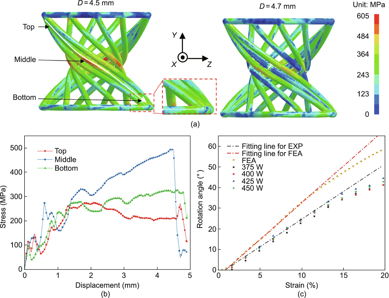
Fig. 10. FEA of the twisting behavior of the CIT-compliant mechanism. (a) Von-Mises stress distribution of the CIT-compliant mechanism before (compression displacement D= 4.5 mm) and after (D= 4.7 mm) fragmentation; (b) Von-Mises stress distribution of three different positions (top, middle, and bottom) on an M–M strut under compression; (c) compressive strain–rotation angle (ε–ω) scatter diagram with fitting lines predicted and obtained by simulation (FEA) and experiment (EXP), respectively.
Fracture morphologies of the specimens processed with different laser powers are shown in Fig. 11. Two different regions—a smooth area and a rough area—can be observed on the fracture surfaces, which can be attributed to the deformation history. A possible analysis is proposed as follows: The rough area on the fracture surface was generated in the non-uniform deformation and yielding stage of the inclined strut during compression. The deformations forming at this stage absorbed most of the energy in the entire compression process. The smooth area on the fracture surface was generated during the subsequent bending and rapidfracture stage of the specimen. Fig. 12 shows optical images of the cross-sectional morphology of the inclined strut processed at a laser power of 400 W after compression. A smooth fracture line corresponding to the smooth area and a zigzag fracture line corresponding to the rough area can be identified on the crosssection shown in Fig. 12(b). Based on the high-magnification scanning electron microscope images shown in Fig. 11, it can be observed that many dimples ranging in size from 5 to 20 μm were generated on the rough fracture area of the specimen processed with a laser power of 375 W. Several pores can also be found on the fracture of this specimen, as marked in Fig. 11(a). As the laser power increased to 450 W, metallurgical defects can no longer be identified, indicating that the difference in the mechanical properties of the specimens processed with different laser powers relates to these defects. Moreover, it is worth pointing out that the rough morphologies formed on the surface of the specimen could act as stress-concentration regions and lead to crack initiation during compression. Thus, it is understandable that the specimen processed with a lower laser power of 375 W was prone to earlier failure compared with the specimen processed with a laser power of 450 W, due to its rough surfaces.
《Fig. 11》

Fig. 11. Scanning electron microscope images showing the morphologies of the fracture surfaces in the middle of the inclined struts. The struts shown here were from samples processed with different laser powers: (a) 375 W and (b) 450 W.
《Fig. 12》

Fig. 12. Optical images of the cross-sectional morphology of the specimen processed with a laser power of 400 W after compression. (a) Overall morphology; (b, c) enlarged images of the marked areas shown in (a), showing the (b) fracture lines and (c) crack propagation, respectively.
《4. Conclusions》
4. Conclusions
In this study, CIT-compliant mechanisms were designed based on the screw theory in the FACT design method. The CIT-compliant mechanisms were then fabricated by means of LPBF using AlSi10Mg powder. The formability (including the relative densification rate, dimensional accuracy, and surface roughness), compressive deformation behavior, and energy-absorption capacity of the LPBFfabricated CIT-compliant mechanisms under different laser powers were studied, and the following conclusions were drawn.
(1) Within a laser power range from 375 to 450 W, changes in the overall relative density of the LPBF-fabricated CIT-compliant mechanism with laser power were not noticeable, and the relative density of samples remained at around 98%. However, increased laser power contributed to eliminating the residual metallurgical pores within the inclined struts.
(2) The dimensional accuracy of the inclined strut exhibited a relatively high level within ±1.5% at all investigated laser powers due to the beam compensation. The surface roughness was influenced by the ‘‘balling effect” and the powder adhesion phenomenon. High laser power weakened the ‘‘balling effect” and decreased the number of partly melted particles adhered to the edge of the inclined strut, thus contributing to a low surface roughness value.
(3) The deformation behavior of the LPBF-fabricated CITcompliant mechanism demonstrated four typical stages: the elastic stage, heterogeneous plastic deformation stage, strengthdestroying stage, and deformation-destroying (or instable deformation) stage. The force–displacement curves of all the LPBFfabricated CIT-compliant mechanisms at different laser powers exhibited a similar result in the uniaxial compression experiments. A mean strain consisting of 4.9% elastic strain and 20% elastic–plastic strain was obtained. Laser power had a limited effect on the maximum loadbearing capacity of the structure. However, with an increase of laser power, the energy-absorbing performance of the CIT-compliant mechanism improved when a large displacement occurred. The CIT-compliant mechanism fabricated at the laser power of 375 W was the first to break in the compression experiment, due to the large quantity of residual pores and high surface roughness.
(4) The CIT-compliant mechanisms fabricated by different laser powers exhibited similar twisting behaviors. An approximately linear relationship between the compressive strain and the rotation angle was achieved before the strain reached 15% for the LPBFfabricated CIT-compliant mechanisms. As the strain increased, the rotation angle per unit of uniaxial strain of the FEA model was larger than the value measured in the compression test. The defects forming in the compliant mechanisms affected their twisting behavior during the compression test. As the strain increased, the rotation angle per unit of uniaxial strain predicted by the FEA model was larger than that measured in the compression test. It was considered that the defects in the compliant mechanisms could play an important role in the mechanisms’ twisting behavior when a large deformation occurred.
《Acknowledgment》
Acknowledgment
This work was supported by financial support from the National Natural Science Foundation of China (U1930207 and 51735005), the Basic Strengthening Program (2019-JCJQ-JJ-331), the 15th Batch of ‘‘Six Talents Peaks” Innovative Talents Team Program (TD-GDZB-001), National Natural Science Foundation of China for Creative Research Groups (51921003), National Natural Science Foundation of China (51905269), and the Priority Academic Program Development of Jiangsu Higher Education Institutions.
《Compliance with ethics guidelines》
Compliance with ethics guidelines
Jie Gao, Dongdong Gu, Chenglong Ma, Donghua Dai, Lixia Xi, Kaijie Lin, Tong Gao, Jihong Zhu, and Yuexin Du declare that they have no conflict of interest or financial conflicts to disclose.


 京公网安备 11010502051620号


