

《1. Introduction》
1. Introduction
Electrorheological (ER) technology aims to control the arrangement of dispersed phases in a dielectric suspension or colloid by applying an electric field to alter the rheological properties, acoustics, transmittance, and other properties of the material [1–4]. The main advantages of this technology are its low energy consumption, fast response within a few milliseconds, and reversible transformation process [5]. These features indicate that the microstructure and macroproperties of these materials can be easily tuned by an external field [4]. ER technology is an advanced technology based on the ER effect. In 1938, Winslow, an engineer in Colorado Springs CO, USA, recorded the ‘‘electroviscosity effect” for the first time while studying a purification process for contaminated oil [2,6]. In 1949, Winslow tried some methods to disperse several different solid particles in insulating oil to obtain different electrorheological fluids (ERFs). He used the term ‘‘electrofibration effect” to describe this phenomenon [6]. In 1972, the first book on electrorheology—Electrorheological Effect, was edited by Academician Luikov [7], and the term ‘‘electrorheological effect” was introduced into the world literature. The ER effect refers to the fact that the rheological properties (such as viscosity, shear stress, shear modulus) of a soft material varies significantly under the application of an external electric field. Upon the introduction of an electric field, there are microstructure changes, such as the oriented arrangement or agglomeration of dielectric particles along the direction of the electric field. After further and extensive study in the areas of physics, chemistry, and materials science, researchers found that not only did the rheological properties of the material change, but also the acoustic, optical, and electrical properties of the material changed as well. Later, research on the ER effect was mainly carried out with ERFs as the carrier [1].
In ER technology, the material with the longest research history is an ERF, which is a smart responsive soft material [4]. By applying an external electric field, its rheological properties change significantly and reversibly. In the decades following Winslow’s discovery of the ER phenomena, various ERFs have emerged. However, poor mechanical properties have restricted the engineering applications of ERFs until 2003, when Wen et al. [8] developed a giant electrorheological fluid (GERF) with a yield strength of up to 130 kPa, and ER technology thus entered a new era. Due to the advantages of low energy consumption and fast response, ERFs are favored by the engineering field. For example, they have been applied in the fields of microfluidic technology, dampers, actuators [9,10], soft robots, brakes, shock absorption systems, and human muscles [11,12]. Although ERFs have been used in some fields, their stability, temperature applicability range, and material sustainability and safety still need to be continuously improved. This is mainly because an ERF is a suspension composed of micro/nanoparticles (NPs) and an insulating continuous phase, and the particles can be easily agglomerated and settled. In addition, for ERFs with higher yield strength, the dispersed phase contains some adsorbed water, which then leads to temperature instability and safety limitations in certain practical applications [13]. However, researchers have made some progress in these issues by exploring the continuous phase [14], adjusting the dispersed phase [15–17] and using additives [18].
Electrorheological elastomers (EREs), another new type of ER material, have an ER effect similar to that of ERFs; that is, their viscoelasticity changes with the applied electric field strength [19,20]. The components of EREs generally include dispersants, additives, and other parts, which have a decisive influence on the properties of the elastomer. EREs are derivatives of ERFs that overcome the shortcomings of sedimentation and the difficult packaging of ERFs. Therefore, the problems encountered in the engineering applications of ERFs are successfully eliminated by the EREs, so they have better application prospects. However, due to the low storage modulus and ER effect, which are still far from the limit of industrial applications, the current research on EREs mainly aims to improve their physical performance. In addition, whether it is ER materials or engineering applications, there are still many problems to be solved. The mechanical properties, stability performance, fatigue resistance, and temperature adaptability of ER materials restrict their wide application. Engineering applications also face severe challenges, such as the packaging of ER materials, the preparation of electrodes, and safety.
Both ERFs and EREs are ER materials prepared based on the ER effect. The changes in the rheological properties of these materials with and without an external electric field are used to prepare smart devices. This is a relatively traditional research idea of using the ER effects to realize applications. With the deepening of research and application, researchers use ER effects to directly change the properties of some materials, so ER technology has also been extended to many other fields. According to the principle of the ER effect, as long as the suspension, colloid, or material in the suspended state contains dielectric particles, the dielectric particles will agglomerate or be arranged in chains or columns along the direction of the electric field after an electric field is applied. Therefore, some properties of these materials can be improved through actions such as a microcontrol, and unexpected results can be achieved. For example, in crude oil transportation [21], because crude oil contains a certain amount of dielectric micro/nanoparticles, these particles will agglomerate or form a chain structure under the action of an external electric field, thus exhibiting a macroscopic effect of reducing viscosity. In addition, this technology has also been applied in food processing [22] and energy material preparation [23]. Especially in the energy field, ER technology has successfully reduced energy consumption and improved the efficiency of crude oil transportation [24]. In addition, this method can also be used to prepare energy storage materials [25]. The development of ER technology has broken the deadlock, which has limited the application of ERFs and expanded the research breadth and application scope of this technology. It has been of great significance to the development of changes in the ER field.
Previously, many scientific researchers have presented reviews of ER technology; for example, Sheng and Wen [3] who organized the theory of ERFs, Dong et al. [4] who reported on the progress research ERFs, Wu et al. [5] and Zhang et al. [26] who published the application of ERFs in microfluidics, and Dong et al. [19] who reported the research progress on ERE. Although these reviews provide a good summary of some of the parts of ER technology, there has not been a comprehensive report in the field of ER technology. This article takes ER technology as the theme and systematically describes the development of ER theory and ER materials, as well as their applications in various fields, rather than summarizing those in only a single field (Fig. 1). Combined with the latest research results, we summarize the future development directions and prospects of ER technology.
《Fig. 1》
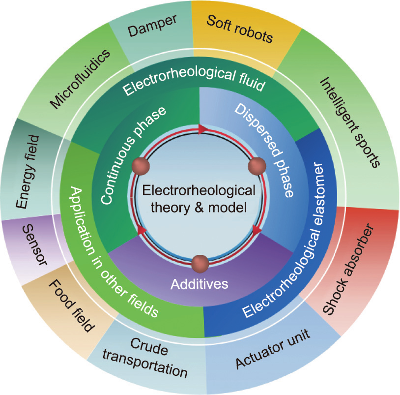
Fig. 1. Outline of the ER technology in this article.
《2. Electrorheological fluids》
2. Electrorheological fluids
Research on ERF materials is currently mainly focused on the selection of the material dispersed phase, particle preparation, and geometric shape adjustment. Continuous phase research has also received extensive attention in recent years, especially the binary-liquid-phase (BLP) ERF model we proposed, which is of great significance to the improvement of the stability of ERFs. The use of additives mainly aims to modify an existing ERF to achieve a certain or comprehensive performance improvement. This chapter will introduce the development of ERF theory and models; research on dispersed phases, continuous phases, and additives; and the applications of ERF.
《2.1. Theory》
2.1. Theory
The general process of the ER effect is as follows [27]: ER particles are polarized under the action of an external electric field, forming a dipole phenomenon. Particles with a dipole moment produce a directional arrangement, which changes the particles from a disordered state to an ordered state, forming a chain or column structure and thereby presenting an external ER effect. An ERF is a complex suspension with a complex composition. Therefore, the cause of and theory of the ER effect are also quite complicated. At present, most scientific researchers believe that the polarization of particles is the main cause of ER effects.
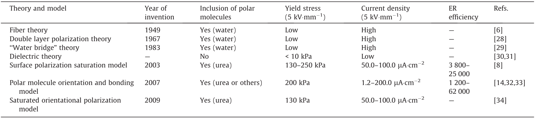
Since the discovery of ERFs, many theories have emerged (Table 1) [6,8,14,28–34]. For example, Winslow [6] proposed the fiber theory in 1949, and Klass and Martinek [28] proposed the electric double layer polarization theory in 1967. Then, Stangroom [29] proposed the ‘‘water bridge” theory in 1983. However, fiber theory cannot explain the slow rate of fibrillation and the difference between the millisecond response times of the ER effect, while the water bridge model and the electric double layer polarization theory can only explain the cause of the ER effect for aqueous ERFs. Currently, the more popular theories are the dielectric theory, the orientation and bonding theory of polar molecules, the saturation polarization model, and the saturated orientational polarization model.
《Table 1》
Table 1 ERF theoretical models and their ER characteristics.
According to the dielectric theory [30], because of the large dielectric constant of the ER particles, an induced polarization occurs under the action of an applied electric field (E). The positive and negative charges of particles move to the negative and positive electrodes, respectively, forming dipoles. Due to the electrostatic force, adjacent dipoles in the dispersed phase attract each other so that the particles form a chain structure. With increasing electric field intensity, the polarization degree of the particles increases, and more particles form a columnar structure, which is stronger than chain-like structures (Fig. 2). Therefore, in terms of macroscopic properties, the rheological properties of ERF change with the strength of the applied electric field.
《Fig. 2》
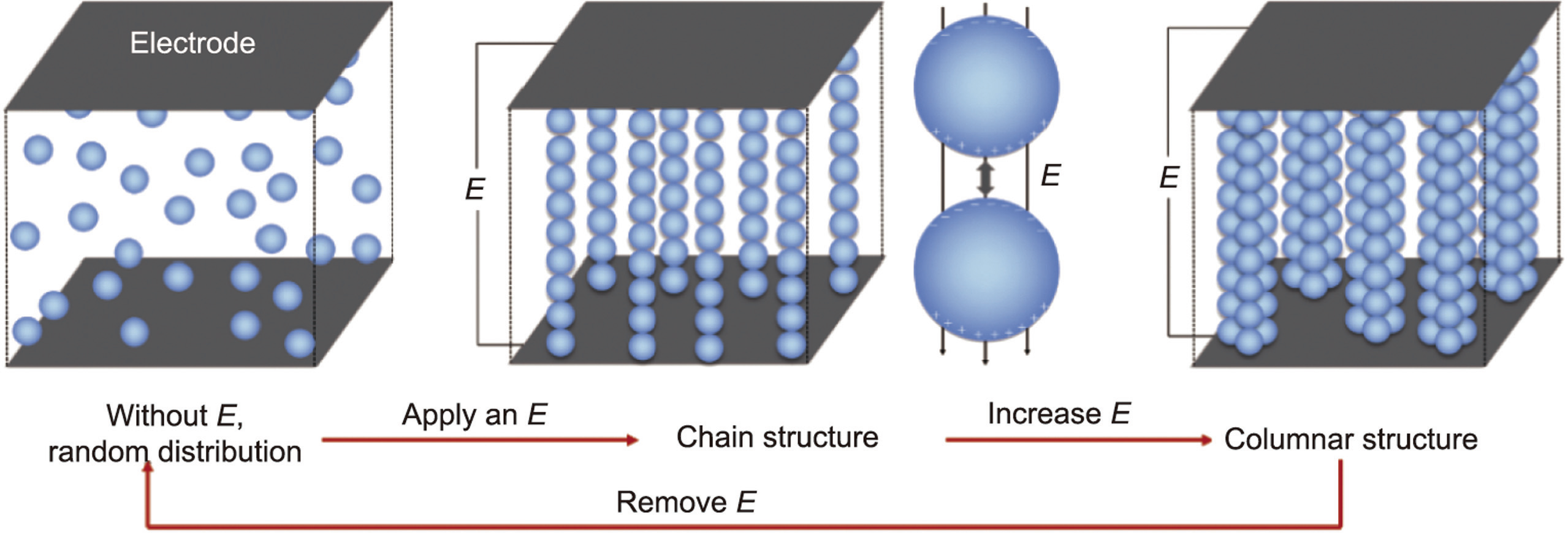
Fig. 2. Particle arrangement according to the dielectric model. E: external strengthening electric field.
The mechanical relationship among particles polarized under an electric field can be approximately described as an electric dipole. In the direction of the applied electric field, the polarization intensity p between particles and the attractive force  between adjacent particles are
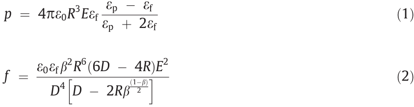
where 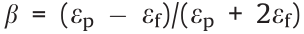 is the dielectric adaptation factor between the dispersed phase particles and the continuous phase liquid, R is the radius of the particles, D is the spherical center distance between adjacent particles, and εp, εf, and ε0 are the dielectric constants of the particles, the liquid, and vacuum, respectively.
However, the theoretical limit of the yield strength of the dielectric-type ERFs is approximately 10 kPa [31], so the dielectric theory is not suitable for high yield strength ERFs. Research on ERFs had stagnated until 2003, when Wen et al. [8] prepared a GERF with a static yield strength of 130 kPa. In addition to its ultrahigh strength and faster response time, the GERF operated with a lower current density over a wide temperature range. The mechanism cannot be explained by the dielectric polarization theory [3]. Therefore, Wen et al. [8] proposed a new theory to explain the giant electrorheological (GER) effect, the surface polarization saturation model.
The surface saturation polarization model considers that GERF nanoparticles are polarized under the action of an external electric field. Due to the electrostatic force, the particles are arranged in an orderly chain structure along the direction of the electric field. When the electric field strength increases to a certain value, a saturated polarization layer will be formed between two adjacent spheres, as shown in Fig. 3(a) [8]. The existence of the saturated polarization layers and the interaction between them improve the stability of the columnar structure composed of the particles, thus allowing the GERF to have high yield strength. Based on this model, using numerical simulation methods, the electrostatic field energy and the elastic interaction energy of adjacent particles are obtained. Then, using these two energy values, the shear strength under the corresponding electric field can be calculated. In their research, the calculated results matched the experimental results very well. The proposed surface polarization saturation model explains the mechanism of the GERF well.
《Fig. 3》

Fig. 3. (a) Saturation surface polarization model, (b) polar molecule orientation and bonding model, (c) saturated orientational polarization model. (a) Reproduced from Ref. [8] with permission; (c) reproduced from Ref. [34] with permission.
Later, TiO2, Sr–Ti–O, and Ca–Ti–O particles with polar molecule modifications were fabricated, and the yield strength was as high as 200 kPa [32]. Unlike urea-coated nanoparticles, these polar molecule-dominated ER particles have no coating and cannot be explained by the saturation polarization model. In 2007, Shen et al. [33] established a polar molecule orientation and bonding model (Fig. 3(b)) to explain these polar-molecular electrorheological fluid (PM-ERF). Particles will form dipoles under electric field-induced polarization, which is induced by an applied electric field, and the adjacent particles will be arranged in chains due to electrostatic forces. The dipoles between the adjacent particles are connected end to end to form a local electric field Eloc (~109 - V·m–1 ) that is much larger than the applied electric field. Then, Eloc promotes the polarization of polar molecules on the particle surface along the direction of the electric field. In this process, the dipole–dipole interaction among the molecules  is much larger than the dipole–charge interaction between the polar molecules and the polarization charge from the particles
  . Therefore, the former is the main cause of the polar moleculedominated ER effect. The orientation and bonding theory of polar molecules is currently applicable to most ERFs with high yield strengths.
In 2009, Tan et al. [34] combined the surface polarization layer model with the polar molecule orientation and bonding model and proposed the saturated orientational polarization model. This model suggests that the GER particles are composed of high dielectric constant nuclei and polarities (Fig. 3(c)). The polar molecule shell layer is further divided into an inner layer and an outer layer, which can be a urea coating layer, a polar molecule, or a polar group. Ions are present on the surface of the dielectric core and interact with the polar molecules, forming a polar molecule shell. The results calculated by the finite element method show that the electric field strength of the outer layer of polar molecules is much stronger than that of the inner layer. The intensity of the local electric field between the two particles is extremely high, ensuring that the outer polar molecules of the particles can be polarized and oriented. Therefore, the saturated orientational polarization of the outer polar molecules is the main cause of a strong interaction between particles under an electric field [34]. This model enriches the theory of GERFs and more comprehensively describes the reasons why GERFs have high mechanical properties. Based on this model, it is proposed that particles with thinner coatings and smaller sizes have stronger ER effects.
《2.2. Fluid model》
2.2. Fluid model
ERFs exhibit Newtonian-like liquid behavior in the absence of an electric field. The application of an electric field causes a transition from a liquid state to a solid state, and the Bingham fluid model was previously used to describe the fluid properties. The Bingham model, shown in Eq. (3), has two parameters originating from yield stress  and Newtonian viscosity
  . The fluid begins to flow when the shear stress reaches a certain value, and its shear stress (
 ) and shear deformation rate (
 ) are linear, similar to a Newtonian fluid.

The Bingham model considers the shear stress to be linearly related to the shear rate. However, the competition between the hydrodynamic breakdown and the attractive force under an applied electric field causes the rheological behavior to be complicated. The Bingham fluid model is not always consistent with the actual flow curve; therefore, other rheological equations have been developed for flow curve analysis, including the Herschel–Bulkley model, De Kee–Turcotte model, Seo–Seo model, and Cho–Choi– Jhon model [35].
Compared with the Bingham model, the Herschel–Bulkley model can also reflect the degree of fluid shear-thinning or shear-thickening behavior. In Eq. (4), m is the consistency index, and n is the fluid shear-thinning index. If < , then the Herschel–Bulkley fluid behaves as a solid; otherwise, it behaves as a fluid. If n < 1, the fluid is a shear-thinning fluid, and the smaller the value of n is, the more obvious the shear-thinning phenomenon. When n > 1, the fluid is a shear-thickening fluid, and the larger n is, the stronger the shear-thickening rheological behavior.

The De Kee–Turcotte model has been widely used to describe the rheological response of various suspension systems, including ERFs, since deviations from the Bingham fluid model have been observed.

Here,  is the shear viscosity for vanishing yield stress at high shear rates, and t is a time constant with units of seconds [36].
The yield stress is the most important variable for the evaluation of ERF performance. However, most models predict only the static yield stress, and there are few studies on dynamic yield stress prediction models. To obtain the static yield stress, Seo et al. [37,38] proposed a four-parameter model as follows:

where  is the static yield stress,
  is the viscosity at a high shear rate,
  is the time constant and is the reciprocal of the critical shear rate at which the rheological behavior changes, and
  is related to the decrease in the stress.
It is often observed that a plateau region appears over a wide shear rate range, with the existence of the minimum shear stress at a relatively low shear rate. A suggested model with six parameters, given below, provides a better fitting of such ERFs as follows:
where, is the dynamic yield stress defined as the stress extrapolated from the low shear rate region, β is the parameter for the high shear rate region, t1 and t2 are time constants, and is the viscosity at a high shear rate and is interpreted as the zero-field viscosity. This model was observed to provide a good indication of the ER characteristics over the whole shear rate range, including the reduced shear stress phenomenon [39,40].
In addition to the abovementioned models, there are many other rheological models, such as the Casson model and Papanastasiou model. Most of these models are empirical formulas that need to be fitted to find suitable parameters for the different types of ERFs, and the mechanical properties cannot be explained theoretically. Generally, these models are only applicable to certain types of ERFs rather than to all ERFs.
《2.3. Research on the dispersed phase》
2.3. Research on the dispersed phase
The dispersed phase can be either a solid or a liquid material, but due to the high cost of liquid materials and poor ER performance, most ERFs use solid particles as their dispersed phase. This phase must have a high dielectric constant, an appropriate conductivity, a feasible density, and relatively stable physicochemical properties. Common dispersed materials include dielectric inorganics, conductive organics and polymers, biopolymers, and liquid crystals [41]. To improve the ER effect of suspensions, various raw ER particulate materials can be further processed via techniques such as surface modification, heat treatment, doping, encapsulation, and hybridization [42]. Early research focused on how to improve the static yield stress of ERFs. The dispersed phase has been the focus of attention of researchers because it greatly affects ER properties. As an important part of the ERF, the conductivity, dielectric constant, volume fraction, size, shape, structure, and geometry of the particles all influence the performance of the ERF.
The solid materials that are selected as the dispersed phase of most ERFs are mainly inorganic nonmetallic, organic, and polymeric semiconductive materials. Organic materials are essentially ionic crystalline materials, while the organic and polymeric semiconductive materials are conductive materials that generally contain conjugated π-bonds. The inorganic materials are usually metal oxides and silicate materials such as TiO2 and aluminum silicate [16]. These types of material have good ER effects, but the current densities of such ERFs are relatively high due to the movement of the metal cations. Most of these materials have high hardness, which causes great damage to devices. In addition, this type of suspension has a great shortcoming, that is, particle sedimentation. In 2021, Kuznetsov et al. [43] prepared deagglomerated nanodiamond particles/polydimethylsiloxane (PDMS) ERFs. For the first time, semiconducting carbon was used alone as the dispersed phase. The functional groups on the surface of nanodiamond particles not only increased the antisettling rate of these ERFs but also made the dispersed phase uniformly dispersed. The emergence of this type of nanodiamond particle/PDMS ERF provides a new idea for the research and development of ERF dispersed phases. In addition, when inorganic material particles are used as the dispersed phase, water is often used as the polar molecule in the ERF. Water can endow an ERF with high yield strength, but the poor temperature range and durability restrict the development of its application [13]. Therefore, researchers have recently tried to find new ways to prepare high yield strength ERFs to expand the scope of ERF applications. For example, Qiu et al. [44] prepared anhydrous TiO2 particles embedded with carbon nanoclusters. They introduced a carbon source (glucose or sucrose) in the process of preparing titanium dioxide particles by hydrolysis of tetrabutyl titanate and carbonized the glucose or sucrose in the particles through high-temperature treatment to obtain TiO2 particles inlaid with nanocarbon clusters. The static yield stress of these anhydrous ERFs increases by 120 kPa (E = 5 kV·mm–1 , volume fraction of 38%), which is larger than that of the TiO2 ERFs (7 kPa). The current density of the anhydrous ERF is only 1.2 μA·cm–2 (E = 5 kV·mm–1 ). The mechanical temperature stability and abrasion resistance of the anhydrous ERFs are excellent. We prepared biomimetic chestnut-like cobalt hydroxide coupled with surfacefunctionalized carbon dots (CDs) particles (Co(OH)2@CDs) by a simple hydrothermal method [45]. Great electrorheological efficiency of the corresponding Co(OH)2@CDs-ERF is about 10 000 (shear rate 0.1 s–1 , 5 kV·mm–1 ). Benefiting from the synergistic effect of the lipophilic groups on the surface of CDs and the biomimetic chestnut-like structure, the zero-field viscosity of Co(OH)2@CDs-ERF is only 0.46 Pa·s (particle mass fraction of 40%). Co(OH)2@CDs-ERF has excellent thermal stability and low current density. In addition, Dong et al. [46], He et al. [47], and Zhao et al. [48,49] also obtained anhydrous ERFs by preparing ERFs with a dispersed phase of hydrophobic poly(ionic liquid) particles.
Conductive organics and polymers are more dispersible in a base liquid than inorganic materials, but the ER effect is weaker. Such materials can be divided into two categories: materials that contain a conjugated π-bond with suitable conductivity and materials that have polarizable groups (hydroxyl, cyano, or amido) on the molecular chain. The former, such as polyaniline (PANI), polypyrrole (PPy), polythiophene, poly(acene quinone) radicals, poly- (phenylenediamine), and oxidized polyacrylonitrile, can be easily polarized under an electric field due to their large dielectric constants. The latter have a large molecular mass and a high charge density. The conductivity of a polymeric material can be adjusted by controlling reaction conditions such as the carbonization temperature, reaction time, and pH [12,41]. However, such ERFs have a relatively high current density and poor dispersion stability due to particle agglomeration. This phenomenon is attenuated by applying a nonconductive organic substance to the surface or by hybridizing the material with an inorganic substance. In addition, in recent years, researchers have adopted the method of coating graphene oxide (GO) on the surface of polymers to improve the dispersion and stability of these ERFs [50–53]. Wang et al. [54] prepared a composite ER polishing particle via Pickering emulsion polymerization, which is formed by polyionic liquid (PIL) ER active particles and commercial Al2O3 nano-abrasives. The method integrates ER active particles and nano abrasives into a particle system, which well overcomes the problem of easy phase separation of the ER polishing liquid prepared by the simple mixing method.
The dielectric properties include the dielectric constant and dielectric loss. There is a boundary point of the dielectric constant: When the dielectric constant is greater than this point, the yield stress of the ERF increases rapidly with increasing dielectric constant and then becomes saturated as the dielectric constant continues to increase. Many factors affect the ER effect, and the performance of ERFs cannot be judged by the dielectric constant only. It has been proven that the ER effects of high dielectric constant materials are not necessarily strong. Only when the particles have a certain dielectric loss can fluids have an ER effect. The dielectric loss has a maximum value in the electric field frequency region from 100 to 105 Hz. The particle conductivity determines the current density, ER effect and response time of the whole suspension. When the dielectric constant of the particles is constant, the higher the conductivity is, the faster the response of the particles. The smaller the conductivity is, the slower the response of the particles, and the ER effect is not obvious [55]. Lee et al. [56] prepared an ERF by dispersing MoS2 nanosheets with different conductivities in silicone oil to study the effect of the particle conductivity on the ER properties. The most suitable conductivity value was found, at which the highest ER efficiency was observed. If the particle conductivity is too high, then the ER response diminishes [57].
Material properties have a huge impact on the performance of ERFs. Similarly, the particle volume fraction of an ERF will greatly affect the yield strength, zero field viscosity, and sedimentation resistance. As the volume fraction of an ERF increases, the number of particles per unit volume increases, the distance between particles decreases, and the particles are more likely to form thick chain and columnar structures, so the yield strength of the ERF is increased [58]. In addition, many body effects exist in ERFs, which increase with increasing concentration and then reach saturation. Consequently, as the interaction force between particles saturates, the shear yield stress will be difficult to increase further [59]. In addition, a particle volume fraction that is too high may lead to lower ER efficiency, which is not beneficial for practical applications. Most studies have shown that the best volume fraction of the dispersed phase is in the range of 0.1–0.4. The yield stress often shows a power law dependence or a roughly linear dependence on the volume fraction in the different ERFs [60]. In addition to affecting the rheological properties, the larger the particle volume fraction is, the better the antisettling performance. As the number of particles in a unit volume increases, the spatial network structure to resist the action of gravity formed by the particles becomes stronger. However, this method will greatly affect the rheological properties of an ERF, so it is not suitable for practical applications.
It is generally believed that the smaller the ERF particles are, the greater the yield stress, as demonstrated by the GERF. Because the overall energy density of a GERF is proportional to 1/R, the yield stress is proportional to the total energy density [61]. However, particles that are too small easily agglomerate, making the zerofield viscosity of the suspension high. In the GER model, the size of the particles should be 10–104 nm. The smaller the size of the particles is in this range, the more obvious the ER effect. In addition, particles with a small particle size easily jump between the two electrodes and enhance the charge exchange under an electric field, showing a higher current density [62].
In addition to the impact of particle size on the performance of ERFs, the various structures and morphologies of the particles also have a huge impact on it, not only improving the ER effect of ERFs but also reducing the zero-field viscosity, reducing the current density, and improving the stability. Therefore, research on particle structure and geometry has also become a research hotspot in recent years. The following summarizes several ERFs with excellent particle structure or morphology.
2.3.1. Core–shell structure
The core–shell structure is the most representative structure and is widely applied in ERFs. ERFs with core–shell particles as the dispersed phase generally have higher ER efficiency and excellent particle dispersion and antisettling properties [63]. Materials with a high dielectric constant are often selected as the core of the particles, which directly affects the yield stress of the corresponding ERF. For example, Wu et al. [64] used SiO2 and TiO2 with different dielectric constants as the core materials of the particles and prepared two types of core–shell structured hydroxyl titanium oxalate (TOC) particles (Figs. 4(a) and (b)). Under the same external electric field, the yield stress of TiO2– TOC ERF is much higher than that of SiO2–TOC ERF. This is due to TiO2 having a higher dielectric constant than SiO2. Therefore, the choice of core material for core–shell particles is particularly important. In addition, the material of the particle shell is diverse, and different materials can be selected as the particle shell to achieve different performance improvement purposes. The particles of the GERF prepared by Wen et al. [8] have this structure: Barium titanyl oxalate nanoparticles are the core, and the outer layer is a urea coating (Fig. 4(c)). It should be noted that the coating cannot be very thick because the saturation polarization steadily decreases with the coating thickness. In addition, Wu et al. [65] used formamide (FA) and N,N-dimethylformamide (DMF) as the outer shell of TiOx particles and prepared two core–shell particles (TiOx–FA and TiOx–DMF) through sol–gel hydrolysis and selfassembly (Figs. 4(d) and (e)). The TiOx–FA ERF shows excellent mechanical properties, and its yield stress is 148 kPa under a 5 kV·mm–1 external electric field. However, when DMF with a lower dielectric constant is used as a shell, the ER properties are relatively low, indicating that the ER properties are positively correlated with the permittivity of the outer shell. Core–shell composite particles have the advantages of both inner and outer layers, showing an enhanced ER effect and dispersion stability. Of course, the shell can also improve the dispersion and antisettling of an ERF as reported by Li et al. [66] who coated nanoparticles–multiwall carbon nanotubes (MCNTs) on the surface of GER particles greatly improving the antisettling properties of a GERF. In addition, using GO to coat the surface of ER particles can also improve the dispersion of particles and the stability of the ERF [67].
2.3.2. Hollow structure
In addition to core–shell structured particles, hollow structured particles are attracting attention due to their low density, high specific surface area and anti-sedimentation performance. Compared with pure particle suspensions, hollow particle-based suspensions show much higher yield stress values under the same conditions [68,69]. The template method is currently the most commonly used method for preparing hollow structures, namely, using micro/nanospheres, porous structures, or other hard materials as a template for the hollow portion. A core/shell composite microsphere is first prepared, and then, the corresponding hollow particle is obtained by calcination or etching. For example, Gao et al. [69] used monodisperse polystyrene (PS) seeds as the core, coated them PANI as the shell, used tetrahydrofuran (THF) to remove the PS core at room temperature, and then washed, filtered, and dried them to prepare conductive polymeric PANI hollow spheres (Figs. 4(f) and (g)). Similarly, Sung et al. [70] used PS as the template for the hollow structure particle core and created the PANI shell through oxidation polymerization. An organic solvent was used to dissolve the PS, thereby obtaining hollow PANI particles. In addition to the common template method, researchers also prepared hollow TiO2 particles with different shapes through the hydrothermal method [68,71]. Li et al. [72] developed a hydrothermal method for preparing hollow TiO2 nanoboxes (Figs. 4 (h) and (i)) using TiOF2 cubes as the precursor. The ER test shows that hollow TiO2 nanobox ERFs exhibit an excellent ER effect and have enhanced ER efficiency. These research results show that a hollow structure has a positive effect on the performance improvement of ERF in all aspects, so this structure is also the main direction of future research and development of ER particles.
Lee et al. [73] first successfully fabricated and adopted doubleshell SiO2/TiO2 hollow nanoparticles (Figs. 4(j) and (k)) as dispersion materials for ERFs to investigate the influence of the shell structure on the ER properties. Yoon et al. [74] also used the same etching method to prepare inverted conducting polymer/metal oxide core/shell structured porous PPy/SiO2–TiO2 nanoparticles (Fig. 4(l)), as well as Mg-, Zn- and Fe-doped silica/titania hollow nanoparticles (ST HNPs) (Fig. 4(m)) [75,76]. The formation process of double-shell hollow nanoparticles (DS HNPs) is shown in Fig. 4(n). First, the Stöber method is used to prepare silica nanoparticles as the core template, and then, the TiO2 shell is coated on the silica core template by the sol–gel method. Then, a layer of SiO2 and a layer of TiO2 are successively coated to obtain SiO2/TiO2/SiO2/TiO2 core/shell nanoparticles (STST CS NPs). Finally, to obtain DS HNPs, the STST CS NPs were etched by sonication with NH4OH. The preparation method of SiO2/TiO2 single-shell hollow nanoparticles (SS HNPs) is similar. As the number of shell layers increases, the interface polarization increases, and the ER performance is significantly improved. As shown in Fig. 4(o), this type of particle structure has a high specific surface area. When an external electric field is applied to the fluid, a strong polarization is generated on the ER particles along the direction of the electric field. Thus, there is a higher polarization force between the particles, which causes a stronger shear stress. The SiO2/TiO2 DS HNPbased ERFs exhibit excellent ER performance, which is 4.1 times that of the SiO2/TiO2 SS HNP-based ERFs (Fig. 4(p)). Moreover, low-density multilayer hollow particle-based ERFs exhibit excellent anti-sedimentation properties. However, the process of synthesizing hollow particles is complicated, and the particles are prone to agglomeration, making it difficult to achieve large-scale production.
《Fig. 4》
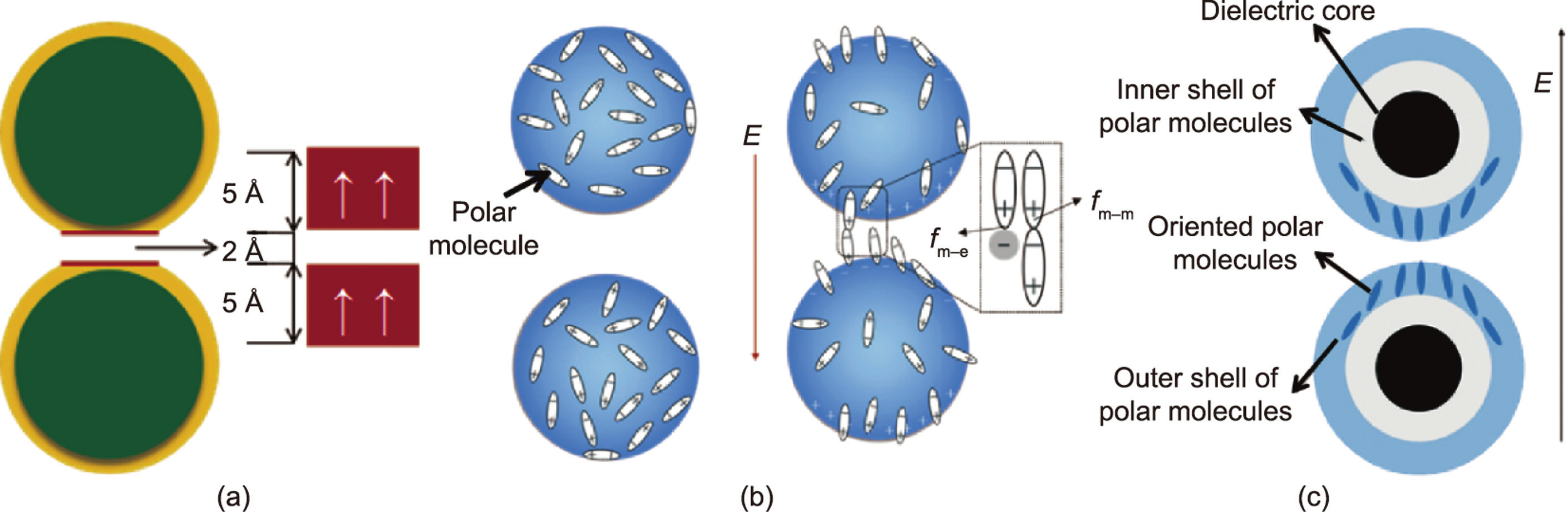
Fig. 4. Scanning electron microscope (SEM) images of (a) SiO2–TOC and (b) TiO2–TOC particles with core–shell structure. (c) Transmission electron microscope (TEM) image of barium titanyl oxalate particles wrapped in urea. (d) SEM image of TiOx–FA particles and (e) TEM image of TiOx–DMF particles. (f, g) TEM images of polymeric PANI hollow spheres. (h, i) TEM images of hollow TiO2 nanoboxes. TEM images of double-shell hollow NPs (DS HNPs) with a diameters of (j) 120 nm and (k) 240 nm. (l) TEM images of porous PPy /SiO2–TiO2 nanoparticles. (m) TEM images of silica/titania (S/T) HNPs. (n) Schematic diagram of the preparation process of SS HNPs and DS HNPs. CS: core/shell; SS: single-shell; SiO2/TiO2/SiO2/TiO2; TEOS: tetraethoxysilane; TTIP: titanium isopropoxide; PVP: polyvinylpyrrolidone. (o) Polarization model of SS HNPs and DS HNPs under applied electric field. (p) Under 3 kV·mm–1 of electric field, the shear stress of SS HNPs ERF and DS HNPs ERF. tres: response time; trec: recovery time. (a, b) Reproduced from Ref. [64] with permission; (c) reproduced from Ref. [8] with permission; (d, e) reproduced from Ref. [65] with permission; (f, g) reproduced from Ref. [69] with permission; (h, i) reproduced from Ref. [72] with permission; (j, k, n, o, and p) reproduced from Ref. [73] with permission; (l) reproduced from Ref. [74] with permission; (m) reproduced from Ref. [76] with permission.
2.3.3. Particle geometry
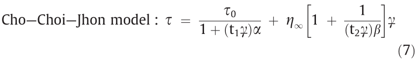
Anisotropic particles show a larger yield stress and lower offstate viscosity than spherical particles. This is due to the geometric effect on the flow resistance and mechanical stability, and the synergistic effect of geometric and dielectric properties that leads to an increase in the ER activity. Due to the large aspect ratio of rod-shaped particles, a larger dipole moment will be generated under an external electric field than with spherical particles, so rod-shaped particles are of interest to researchers [77]. For example, Lee et al. [78] prepared silica rod-shaped particles coated with GO (Fig. 5(a)). In addition, the aspect ratio of particles was changed to study the effect of particle geometry on ERF performance. As a result, rod-shaped particles with a large aspect ratio were found to exhibit a larger dielectric constant and shorter relaxation time for interfacial polarization. Wu et al. [79] prepared surfactantmodified calcium titanyl oxalate (SCTO) particles with a rodshaped structure (Fig. 5(b)). The obtained SCTO ERF has a high yield stress, which is approximately twice that of the spherical calcium titanyl oxalate ERF, and it also has a lower zero-field viscosity, thereby achieving a higher ER efficiency. The higher ER activity is largely due to the rod-like geometry of SCTO.
In addition to rod-shaped particles, particles with different shapes can also improve the performance of ERFs when used as the ERF dispersion phase. These unique morphologies enlarge the surface area, which leads to improvement of the interfacial polarization and ER activity. For example, researchers also prepared chrysanthemum-like particles (Fig. 5(c)) [80], flower-like TiO2 particles wrapped with MoS2 flakes (Fig. 5(d)) [16], cactus-like titanium dioxide particles (Fig. 5(e)) [81], and nanoclip-like PANI particles (Fig. 5(f)) [17]. ERFs were prepared from these particles with different geometric shapes as the dispersed phase. Their ER properties are much higher than those of the ERFs using spherical particles of the same materials. Some geometric particles can not only improve the ER properties of ERFs but also have a positive effect on the stability of the dynamic shear stress of ERFs. Wu et al. [82] prepared titanium titanyl oxalate (TTO) particles with a tremella-like wrinkly microstructure (W-TTO) without adding surfactants (Figs. 5(g) and (h). Compared with the original TTO ERF, the W-TTO-based ERF exhibits enhanced ER activity because the wettability between W-TTO and silicone oil was improved. More importantly, the dynamic shear stress of the spherical TTO particle ERF decreases as the shear rate increases (Fig. 5(i)), but the dynamic shear stress of the W-TTO ERF remains stable throughout the shear rate range (Fig. 5(j)).
Mixing different forms of particles, compared to a single particle system as a dispersed phase, will have a better ER effect. For example, Yoon et al. [15] observed a mixed geometrical effect by mixing SiO2 spheres and rods of different dimensions (Fig. 5(k)). The bimodal ERFs composed of small spheres and rods with a high aspect ratio at a low concentration of the spheres exhibit ER efficiencies that increased by as much as 23.0% more than the corresponding single SiO2 rod-based ERF. This is mainly because the rod-like materials form highly linked fibril-like structures and the spheres reside near or fill in the spaces between the fibrillated rods. Among these forms, the nano-ER material can induce higher ER activity, and the rod-like material can effectively produce mechanical stability. Under the synergistic effect of the two types of particles, the ERF not only has good ER properties but also has higher antisettling properties [15]. In addition, Wu et al. [83] reported a novel micro/nanoparticle hybrid calcium titanyl oxalate (HCTO) ER material composed of micron-sized spindly particles and nanometer-sized irregular particles (Fig. 5(l)). Due to the geometric structure at both ends of the jujube-shaped particles, a stronger local electric field can be formed between the particles under the action of an external electric field, resulting in a stronger induced dipole moment and increasing the force between the particles. Meanwhile, the nanoparticles accumulate at the junction of the spindly microparticles, forming a more intense geometry in a manner similar to concrete structures (Figs. 5(m) and (n)). Moreover, such bimodal systems have low sedimentation rates that are slightly larger than the sedimentation rates of single nanoparticle component systems [83].
《Fig. 5》
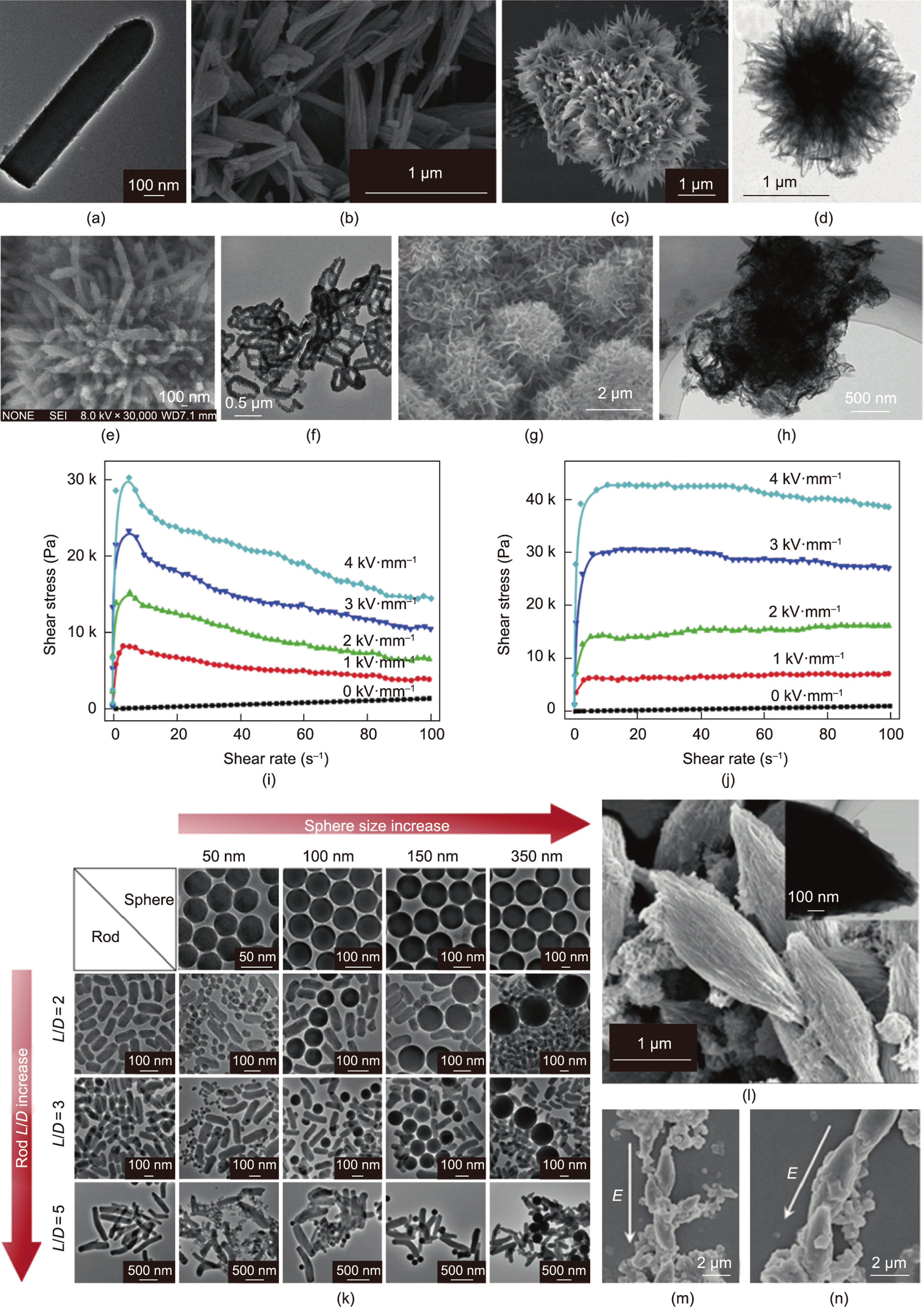
Fig. 5. (a) TEM image of a GO-wrapped silica rod; (b) SEM images of SCTO particles; SEM images of (c) chrysanthemum-like particles and (d) flower-like nanostructure; (e) SEM images of cactus-like particles; (f) TEM images of nanoclip-like PANI particles; (g) SEM image of W-TTO; (h) TEM image of W-TTO; Under different electric field strengths, the shear stress of (i) TTO and (j) W-TTO ERFs with a volume fraction of 32% varies with the shear rate. (k) TEM images of SiO2 spherical particles with different sizes and SiO2 rod-shaped particles with different aspect ratios and their mixtures; (l) SEM image of the spindle particle and its TEM image (inset); (m, n) SEM images of the structure composed of HCTO particles under an external applied electric field. (a) Reproduced from Ref. [78] with permission, (b) reproduced from Ref. [79] with permission; (c) reproduced from Ref. [80] with permission; (d) reproduced from Ref. [16] with permission; (e) reproduced from Ref. [81] with permission; (f) reproduced from Ref. [17] with permission; (g–j) reproduced from Ref. [82] with permission; (k) reproduced from Ref. [15] with permission; (l–n) reproduced from Ref. [83] with permission.
《2.4. Research on the continuous phase》
2.4. Research on the continuous phase
The continuous phase is also referred to as the dispersed phase. According to dielectric theory, a dielectric mismatch relationship between the dispersed phase and the continuous phase is first required. Furthermore, an ideal continuous phase should have the following characteristics: low volatility, high chemical stability, high boiling point, low freezing point, high puncture resistance, low viscosity, and proper density matched to the dispersed phase. If the density of the oil phase is equivalent to the density of the particles, then the ERF will not settle. Unfortunately, no suitable high-density carrier liquid has been found thus far. The continuous phase has a great influence on the performance of ERFs, therefore due to the stable performance of silicone oil, it is currently widely used as the continuous phase of ERFs. There have been relatively few studies on the continuous phase of ERFs, but recently, researchers have achieved significant improvements in the ER efficiency and antisettling performance through the interaction of the continuous phase and the particles. The following sections will introduce two types of studies: those on common single-liquidphase (SLP) ERFs and those on the recently introduced BLP ERFs [14].
2.4.1. SLP ERFs
The most widely used continuous phase of SLP ERFs is dimethyl silicone oil [84]. Researchers found that the particles more easily align in the direction of the electric field to form a stable and firm columnar structure, resulting in a more remarkable ER effect at a low electric field strength. Additionally, a less viscous oil-based ERF has higher ER efficiency because of its low zero-field viscosity. Nevertheless, using high-viscosity silicone oil as the continuous phase of ERFs has the following two advantages: lower leakage current density and superior reversibility.
In addition to viscosity, some scholars found that the protruding end group of the oil phase has a direct impact on the ER effect. The zero-field viscosity and yield stress values can be adjusted by continuously changing the terminating functional group. For example, GERFs with hydroxyl-terminated silicone oil have the highest yield stress values compared to methyl or diglycidyl group-terminated silicone oil. Since the terminal hydroxyl group is small, the steric hindrance effect on particle aggregation is also small, which is advantageous for the aggregation of particles in an electric field. On the other hand, the terminal hydroxyl group has a certain polarity, and a certain orientation will occur under the electric field. This enhances the aggregation of the particles, forming a thicker chain structure and producing a large shear stress. At the same time, the action of hydrogen bonds tends to cause the particles to form larger clusters, thereby slightly increasing the zero-field viscosity of the ERF [85,86].
Due to the different wetting characteristics between the dispersed and continuous phases of the ERFs, after mixing they tend to exhibit an apparent fluid-like viscosity, much like a clay or gel. Generally, the better the wettability between the particles and the continuous phase, the lower the viscosity of the prepared ERFs and the better the ER effect. Because particles with poor wettability cannot be well dispersed in the continuous phase, solid–liquid separation easily occurs, resulting in ERFs exhibiting a higher zerofield viscosity. However, particles with excellent wettability can be well dispersed in the continuous phase without excessive agglomeration, which is conducive to the formation of local electric fields between particles [87–91]. In addition, good wettability is helpful for obtaining ERFs with low current densities and low sedimentation rates for practical applications. This has recently been confirmed. Wu et al. [82] found that the current densities of ERFs that possess good wettability are obviously lower than those with inferior wettability. For the poor-wetting case, electrons can easily move through particles that are in close contact. For particles with better wettability, the continuous phase can be well placed on the surface of the particles to form a better insulating layer, thereby limiting the migration under the action of an external electric field and achieving the effect of reducing the current density.
2.4.2. BLP ERFs
For a single continuous phase ERF, changing the continuous phase usually improves only one of its properties. For example, although the viscosity of the ERF can be reduced when using lower viscosity silicone oil as the continuous phase of an ERF, its antisettling performance deteriorates. Therefore, the use of two or more liquids, utilizing their different properties in terms of particle wettability, can simultaneously improve the performance of an ERF.
We mixed alkane and silicone oil according to a certain ratio as the continuous phase of GERF. By this simple method of changing the continuous phase, we prepared BLP GERFs. (Fig. 6) [14]. Due to the very different surface wettability of GERF particles to the binary liquid phase and the hydrophobic interaction between the alkane molecules and the particles, the dispersed particle size distribution is broadened. Therefore, the ER efficiency of BLP GERF is as high as 10 656, which is 1.8 times that of SLP GERF. In addition, its viscosity is extremely low, while its stability is still excellent. Moreover, the GERF concentration variations along the vertical direction were measured by tracking the backscattered light intensity. We tested the long-term stability of BLP GERF and found that over 100 d, BLP GERF exhibited excellent antisettling performance and stability.
《Fig. 6》

Fig. 6. Distribution of dispersed and continuous phases in BLP GERF. Reproduced from Ref. [14] with permission.
《2.5. Research on additives》
2.5. Research on additives
Additives are used to enhance the stability of the particles in the liquid phase, increase the dielectric constant of the particles, and improve the wettability between the particles and the continuous phase. The amount of additives is small (0.01 wt%–5.00 wt%), but it can have a great effect on ERFs. Various surfactants are common additives, such as anionic surfactants, cationic surfactants, and nonionic surfactants.
Surfactants are amphiphilic compounds composed of nonpolar long chain hydrophobic groups and polar hydrophilic groups. At an oil–water interface, the hydrophilic end is dissolved in the water, and the hydrophobic end is dissolved in the oil, thus forming an aligned monolayer. The hydrophobic groups of different types of surfactants have relatively small structural differences and generally branched or linear chains. Common hydrophobic groups include the –CH chain, the –CF chain and –Si. The hydrophilic end is a hydrophilic inorganic salt or a polar organic substance of various types with large structural differences. Common hydrophilic groups are –OH, –COOH, –CONH2, and so on. The hydrophilic end of an anionic surfactant is anionic, which is the earliest and most widely type of used surfactant. The common types mainly include carboxylates, phosphate salts, sulfate salts, and so on. The hydrophilic end of a cationic surfactant is a nitrogencontaining cationic group, and ammonium salts and quaternary ammonium salts are the most commonly used. The hydrophilic end of a zwitterionic surfactant contains both negative and positive ions. Such a surfactant is cationic in an acidic solution and anionic in an alkaline solution and is usually of the amino acid type or betaine type. Nonionic surfactants do not dissociate and become charged in water, their hydrophilic groups are mainly ether groups and free hydroxyl groups, and the common ones include the polyoxyethylene type and polyol type [92]. The amount of surfactants is critical: Too little cannot provide an enhancement, whereas excessive free additives cause a sharp rise in the current density [18].
Because the method of using additives to improve the performance of ERFs is simple and the role of additives is enormous, the effects of many types of additives on ERFs have been studied [91–94]. For example, Shen et al. [88] added oleic acid at 0.03 vol% into poly(a-olefins) before mixing with particles, which resulted in completely different fluid characteristics. As a result, the fluid, which did not have an ER effect previously, achieved a high yield stress of 260 kPa at 3 kV·mm–1 . In addition, Wang et al. [91] reduced the particle size and improved the wettability of titanium oxide particles in a base liquid by adding sodium dodecylbenzene sulfonate (SDBS), and the ER property was improved. Qiao et al. [94] reported that after adding an appropriate amount of sodium dodecyl sulfate, the suspension had excellent antisettling properties. Xu et al. [95] studied the effect of surfactant Span on the particle–oil interaction and agglomeration effect of GERF.
Xu et al. [18] modified the surface of GER particles by adding silicone polyether (ofx-0309 and ofx-0400) for performance tuning. The basic preparation process is shown in Fig. 7. Applying surfactants for adsorption at the solid–liquid interface can lead to the conformation of an adsorption layer on the GER particles, which can well cover the exposed polar molecules on the surface and effectively reduce the leakage current density. The addition of silicon polyether weakens the yield stress of the GERF, but it improves the dispersion and stability of the particles in silicone oil. Furthermore, the addition of an appropriate amount of silicone polyether is beneficial to reduce the leakage current density of a GERF. After weighing various properties of the GERF, the most balanced GERF was prepared by changing the type and amount of the surfactant. This approach is very instructive because it provides repetitive stability and a wide range of industrial applications [18].
《Fig. 7》
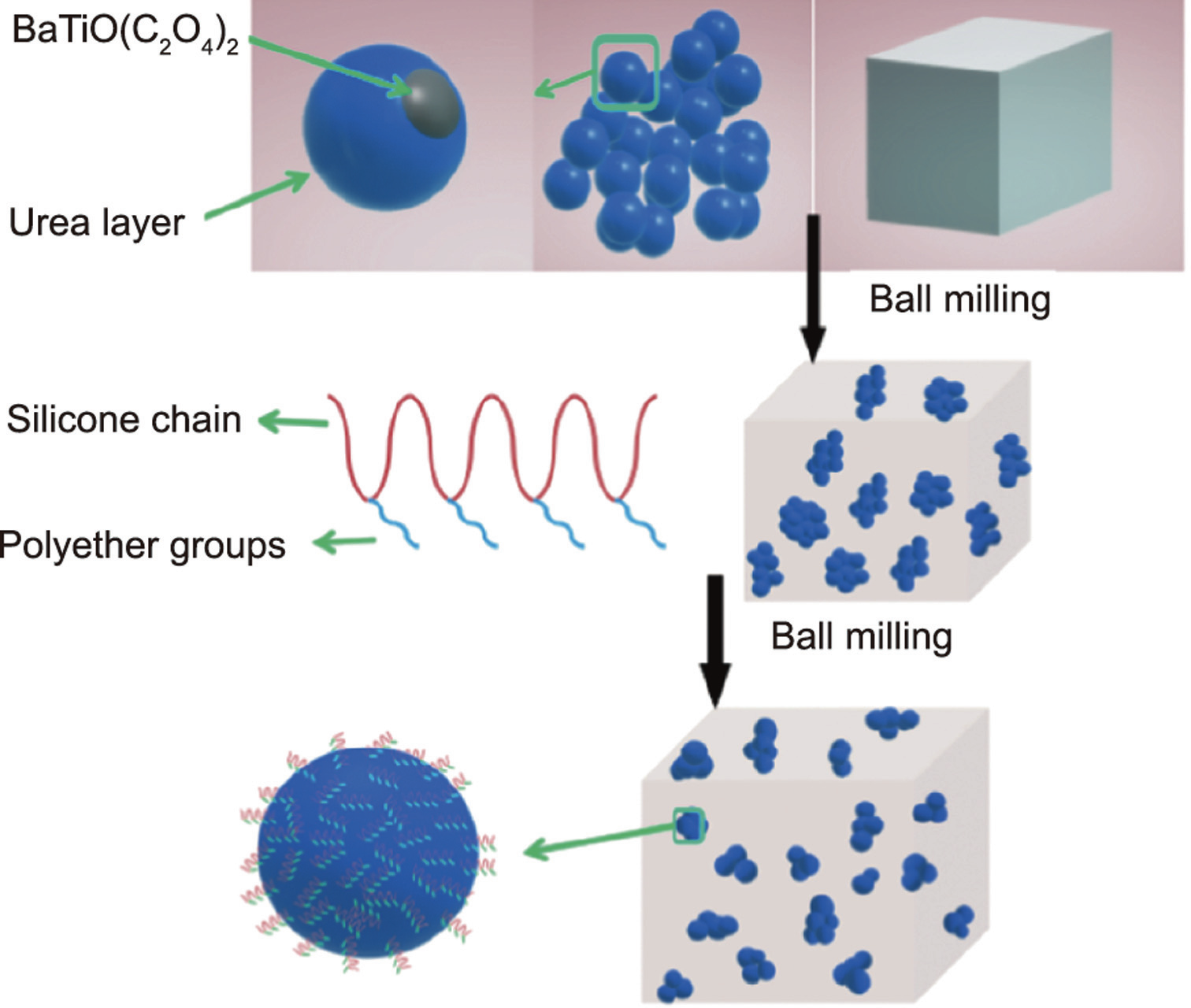
Fig. 7. Schematic diagram of the method of using silicone polyether to improve the properties of GERF. Reproduced from Ref. [18] with permission.
《2.6. Application of ERFs》
2.6. Application of ERFs
ERFs have been widely used in the engineering field. Here, we briefly introduce its application in microfluidic technology and dampers in recent years.
2.6.1. Application of GERFs in microfluidics
In the late 1990s, Manz et al. [96] proposed the concept of a ‘‘total chemical analysis system (μTAS)”, emphasizing the importance of microdevices in chemical and biological testing. Among the many branches derived since then, microfluidics has paid more attention to fluid transport phenomena, microdevice design, and application at the micron scale. To develop different microfluidic functional components, GERF has been used as an efficient smart medium due to its strong response to an electric field (millisecond level).
When introduced into microfluidics, GERF could control other fluids in two modes: the noncontact mode—the two kinds of fluid flow in different channels where GERF will influent the controlled fluid by pushing or pulling a thin diaphragm between them; and the contact mode in which GERF and the controlled fluid flow in the same channel and ‘‘smart” droplets are generated and controlled. GERF in microfluidics could be used to control either continuous fluid or single droplets, bringing about functional components such as microvalves, micromixers, microrectifiers, and microfluidic logic gates.
As the shear stress of the GERF can reach more than 100 kPa under a certain applied electric field, GERF microvalves [97] were designed to control other flow channels. A diaphragm was inserted between the GERF channel and controlled channel, and two pairs of electrodes were embedded on the GERF channel sides, one upstream of the diaphragm and the other downstream. If a sufficiently large electric field is applied to the downstream electrodes, the viscosity of GERF will increase, and the diaphragm will experience certain deformation, which will block part of the controlled channel, decrease the flow rate or even cause closure of the channel. In contrast, when an electric field is applied to the upstream electrode pair, the pressure decreases, and the diaphragm expands on the GERF side to open the controlled channel, as shown in Fig. 8(a) [98]. Thus, the controlled channel could be regulated according to the application of an electric field.
《Fig. 8》

Fig. 8. Applications of GERFs in microfluidics. (a) Diaphragm control for microvalves, micropumps, and micromixers; (b) micro rectifier structure and direction of fluid movement; (c) schematic view of two types of smart droplets.  : pressure differential generated by smart droplets under an electric field. (d) Schematic view of a logic gate circuit in microfluidic. V1–V4 are the voltages applied to pads 5, 6, 1, 2; VA and VB are the electric potentials on either side of the output GERF channel; ZA and ZB are the impedances provided by signal channels A and B, and ZE is the GER fluid impedance. (a, c) Reproduced from Ref. [98] with permission; (b, d) reproduced from Ref. [99] with permission.
By combining three microvalves together, a GERF micropump has been designed to regulate the flow rate of a fluid in microchannels with programmable digital control [99]. Applying a voltage of different polarity on the three pairs of electrodes could control the three diaphragms to inflate or deflate, resulting in the controlled flow of the fluid. A GERF micropump can realize automatic fluid flow and circulation, and the flow rate could also be changed with the adjustment of the deformation rate of the three diaphragms. With its simple design, flexible control, and good biocompatibility, GERF micropumps have wide application prospects, such as stable flow transportation in microfluidics detection systems, circulating flow construction in biochips for washing cells or polymerase chain reactions, and cooling components in microdevices.
Laminar flow (Re < 2000) and electroosmosis are the main characteristics of fluids at the microscale. Two fluids cannot mix well in a microfluidic chip. GERF micromixers [98] were invented to achieve effective fluid mixing in microchannels. Several side channels with GERF valves were designed on both sides of the fluid channel. When an electric field is applied, side channels alternately push and pull, increasing convection in the main fluid channel. As a result, chaotic mixing can be achieved by controlling the frequency of the electric field.
Because of the reversibility of viscous fluids, it is difficult to obtain fluid rectifiers through geometric asymmetry without any external forces. In a GERF-based micro rectifier [100], the irreversibility of viscous fluid could be realized by combining a spatially e asymmetric structure with an electric field. Under proper conditions, the channel will be blocked when the GERF flows in the forward direction (from left to right), while it can pass through the channel smoothly when flowing in the opposite direction (from right to left), as shown in Fig. 8(b) [99]. This function is similar to a ‘‘fluid diode,” which can realize the one-way flow of a fluid.
When applied to the droplet microfluidic system, GERF could not only be dispersed in the carrier fluid as smart droplets [101] but could also be used as a smart carrier to control other droplets or bubbles [102], as shown in Fig. 8(c) [98]. When a pair of electrodes are embedded beside the microchannel, the space between them can be considered an impedance of a circuit, and the difference in the dielectric constant between the droplet and the carrier could use electrical signals to detect droplets or to trigger other operations in nearby fluid channels. In this way, smart droplets can communicate with each other, and a droplet logic gate can be realized, as shown in Fig. 8(d) [99,103]. GERF-based microfluidic droplet control is summarized in the review of Wu et al. [104].
2.6.2. Damper applications
Since their emergence, ERFs have been widely used in the field of vibration suppression, such as in dampers. The research on ERF dampers can be mainly classified into three fields: structural design, mathematical model building, and control algorithm study. In the early stages, researchers focused on the structural design of dampers. To exert the advantage of the tunability of an ERF, the study of the control algorithm has been brought into focus, which can achieve a better vibration control effect. Hasheminejad et al. [105] proposed an exact model of sound transmission for a sandwich cylindrical shell that included a tunable ERF core. The active control method based on this model could lay a foundation for solving the vibration problems encountered in the engineering application of cylindrical shells. The basis of the control algorithm is to build an accurate mathematical model for the ERF and the damper. Zhao and Xu [106] proposed a hysteretic model that can be used for reference when building a model for an ER damper.
Since GERFs were discovered, they have broken the performance limits of ERFs, with better prospects in engineering applications. Researchers applied GERFs to devices such as dampers to improve their mechanical properties. Pu et al. [107] used a GERF under the compression mode and demonstrated the outstanding performance of the GERF. As seen in Figs. 9(a) and (b), a type of multiple plate electrode GER damper operating in compression mode was proposed in this paper. Experiments were carried out to prove the mechanical properties of the damper. Changes in both the damping and stiffness were observed in the results, which showed superiority in engineering applications compared with the traditional ERF damper.
《Fig. 9》
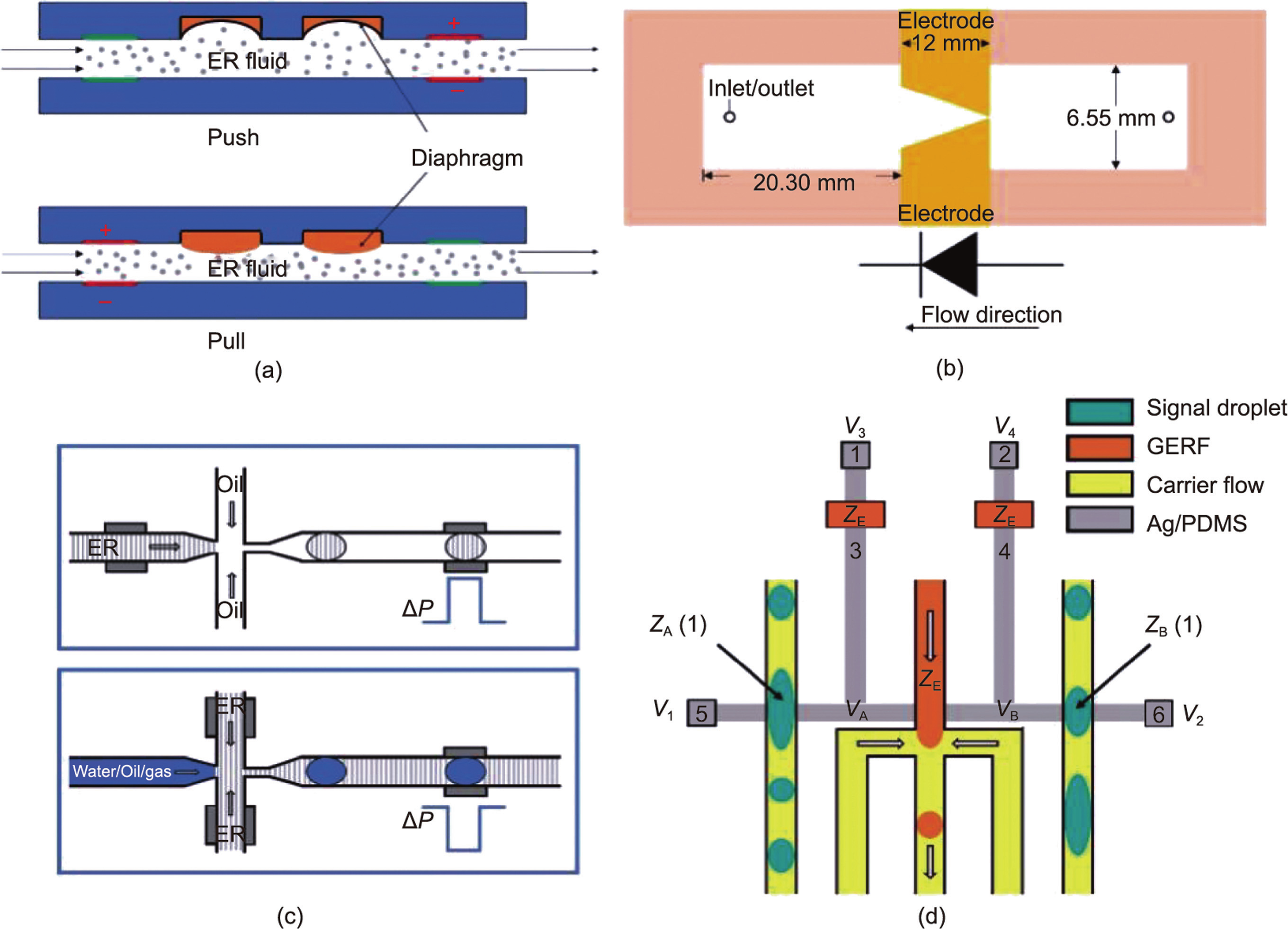
Fig. 9. (a) Schematic and (b) physical image of the GER damper with multiple plate electrodes in compression mode. Dc, Dpo, Dni, Dso, and Ht refer to the central shaft set, the positive plate electrode, the negative plate electrode, the shell, and the total size, respectively. (c) Structure of the GERF damper under shear mode. v: shear direction. (d) Transmissibility results of the GERF damper. (a, b) Reproduced from Ref. [107] with permission; (c, d) reproduced from Ref. [108] with permission.
Sun et al. [108] built an improved hysteretic model for GERF dampers under shear mode, which promoted the development of engineering applications of GERFs in vibration suppression. With the enhanced mechanical properties of the GERF, a damper composed of multiple electrodes operating under shear mode was proposed, as shown in Fig. 9(c). This damper exhibited an outstanding performance of high damping and low stiffness. In addition, an improved mathematical model was proposed in this paper, and the results showed that the model could well describe the mechanical performance of the GERF. Vibration suppression experiments were also conducted to demonstrate the effect of vibration suppression. The test data show that the GERF damper has an excellent damping effect, can not only reduce the vibration by 91.3% but also has a higher adjustable range of 43.8%, as shown in Fig. 9(d). This fully proves that the GERF damper has high practical value.
《3. Electrorheological elastomers》
3. Electrorheological elastomers
As a derivative of ERFs, EREs possess an ER effect similar to that of ERFs, and their stiffness increases with the application of an electric field. Problems such as agglomeration and leakage can be avoided in EREs, rendering EREs of wide interest.
《3.1. Theoretical research on EREs》
3.1. Theoretical research on EREs
ER effects occur in EREs as follows: With an applied electric field, the particles of EREs generate polarization and are regarded as dipoles; thus, the parts with different particle charges attract each other, and they are arranged in chains along the orientation of the applied field or have a tendency toward chain formation, thus improving the stiffness of the EREs. The ER properties of EREs were evaluated by appropriate indices, and the interparticle interactions were analyzed.
In evaluating the ER performance of EREs, the shear storage modulus (G' ) and shear loss modulus (G' ') of the elastomer increase with increasing electric field intensity. Thus, the incremental storage modulus  ( =
( =  –
–  , where and are the shear storage modulus of the elastomer with or without application of an electric field) can be an index for ER performance evaluation of EREs. In addition, the relative ER effect (
 ) can also be used to evaluate the ER performance of EREs.
Studies have simulated and analyzed the viscoelasticity of EREs. Ma et al. [109] modified the Bouc–Wen phenomenological model to give a precise description and prediction of the nonlinear viscoelastic behavior of EREs at low shear frequency and sinusoidal shear strain, which can also be extended to describe the situation of different low-frequency harmonic loads. Due to the inherent properties of EREs, they can be used as damping devices. Niu et al. [110] researched the damper performance of EREs and proposed a theoretical model that was confirmed by experimental results. According to the model analysis, it can be concluded that interface damping dominates the damper performance of EREs filled with modified TiO2 particles at high strain amplitudes and high particle contents. At low strain amplitudes and low particle contents, the intrinsic damping makes a difference. The theoretical model is helpful for preparing EREs with better damping properties.
The attraction between particles under an electric field is the main cause of the ER effect of EREs. According to conventional ER theory, the polarized particles are assumed to be pellets, and the interaction between the pellets is replaced by a dipole with the same strength under the electric field. Then, the electrostatic force (F) between adjacent particles under the electric field can be expressed as [19,111]
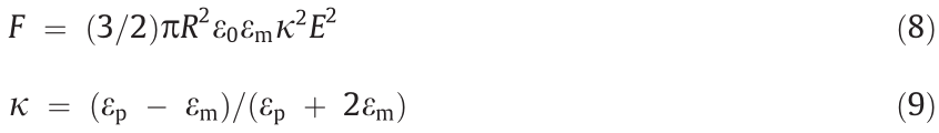
where κ is the dielectric mismatch; εm is the relative permittivity of the particle and matrix, respectively. According to Eqs. (8) and (9), of the ERE after applying the electric field can be calculated as [19]

where φ represents the volume fraction of the dielectric particles. Eq. (10) shows that the storage modulus increment of conventional ER particle-filled EREs under an electric field is proportional to the quadratic electric field intensity, namely, 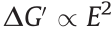 .
.
ER particles coated with polar molecules are more in line with the saturation surface polarization or orientational polarization model. The interaction between adjacent particles under an electric field is dominated by the local electric field force (Fm–e) and expressed as [111]

where N is the number of oriented polar molecules, A is a constant and related to the properties of the particle and the oil, ρ is the area density of the polar molecules adsorbed on the particles, e refers to the fundamental charge, and μ and d are the intrinsic dipole moment and the size of the polar molecules, respectively. Eq. (11) shows that the storage modulus increments of the EREs filled with polar molecule-coated ER particles under an electric field are proportional to the electric field intensity, namely,  E. It is theoretically explained that the interaction between ER particles coated with polar molecules grows faster than that between conventional ER particles when the electric field intensity increases.
《3.2. Composition of EREs》
3.2. Composition of EREs
Generally, EREs comprise a dispersed phase, a continuous phase, and additives, which determine the properties of elastomers. The dispersed phase in EREs is the same as that used in ERFs with a high permittivity, a strong polarization under an electric field and good ER properties. In recent years, studies on ERE dispersed phases have mainly focused on inorganic solid particles, such as TiO2 [112–114] and BaTiO3 [115,116]. The ER effect is mainly due to the interaction force caused by the polarization of ER particles, and thus, as the dispersed phase of EREs, ER particles dominate the variation in the viscoelasticity of the EREs under an electric field.
ER particles play a major role in ER materials because their polarization and interaction in an electric field are the main causes of ER effects. Therefore, the synthesis of ER particles with excellent performance is a major research direction. Yuan et al. [117] used particles with a GER effect as the dispersed phase, PDMS as the dispersant, and silicone oil as the plasticizer to produce EREs. The particles were BaTiO(C2O4)2 coated with a polar molecular layer (urea) and prepared by an improved coprecipitation method. The synthesized ERE has the highest relative ER effect at present; that is, the storage modulus of the ERE under a 3 kV∙mm–1 electric field is increased by 3280% than that without an electric field. Studies have noted that the polar molecular outer layer of particles is conducive to enhancing the ER effect, which is part of the reason for the excellent ER properties of elastomers containing GER particles. Niu et al. [112] researched EREs filled with TiO2 particles coated with urea, and the results showed that the polar molecular outer layer of the particles is useful for the ER effect.
In terms of the surface modification of particles, Dong et al. [113] modified TiO2 particles by using two silane coupling agents, 3-(trimethoxysilyl)propyl methacrylate and triethoxyvinylsilane. Compared with bare TiO2 particles, the modified TiO2 particles combined with silicone rubber better and improved the storage modulus and relative ER effect of EREs.
Similar to ERFs, different particle morphologies have a great influence on the mechanical properties of EREs. From the perspective of the particle shape and structure, Gao et al. [115] obtained Mg-doped BaTiO3 particles with different morphologies by using a hydrothermal method with the aid of a Ba–ethylenediaminete traacetic acid (EDTA) chelating precursor and tuned the reaction temperature and pH value. The hydrophilicity order was sea urchin > pit-like > spherical, and the permittivity of the three particles was in the order of pit-like > spherical > sea urchin. Complying with the dielectric polarization mechanism, an asymmetric morphology and crystal defects of particles augment the polarizability of particles in an electric field, so the pit-like particles with the highest asymmetry and crystal defects have the highest dielectric constant. Comparing the shear storage moduli of the elastomers filled with a BaTiO3 content of 1 wt% gelatinized with and without an electric field, the results show that the storage modulus increments of pit-like BaTiO3-filled and sea urchin BaTiO3-filled elastomers are higher than that of spherical BaTiO3- filled elastomers. Fig. 10 [116] show poly(methylmethacrylate) (PMMA)@BaTiO3 particles with a core–shell structure synthesized by a self-assembly method, in which the BaTiO3 particles and the PMMA microspheres modified by a silane coupling agent combine to synthesize PMMA@BaTiO3 with different contents of BaTiO3 and a core–shell structure by controlling the mass ratio of BaTiO3 and PMMA. Then, a PMMA@BaTiO3/gelatin/water elastomer with a particle content of 1 wt% was successfully prepared. However, in these two studies on the shape and structure of particles, it is necessary to test the storage moduli of the EREs in an electric field and obtain the relative ER effect to specifically explore the influence of the shape and structure of particles on the ER performance of the EREs. Changes in the particle shape and structure can result in changes in the dielectric properties of particles, which affects the response of EREs to an electric field. To date, a few studies have shown that the ER properties of EREs can be significantly improved by obtaining particles with novel shapes and structures. The influence of particle geometry and structure on the mechanical properties of ERE is mainly attributed to the different dielectric constants of particles with different geometric morphologies. The effect of geometry on the performance of EREs remains to be further explored by researchers.
《Fig. 10》
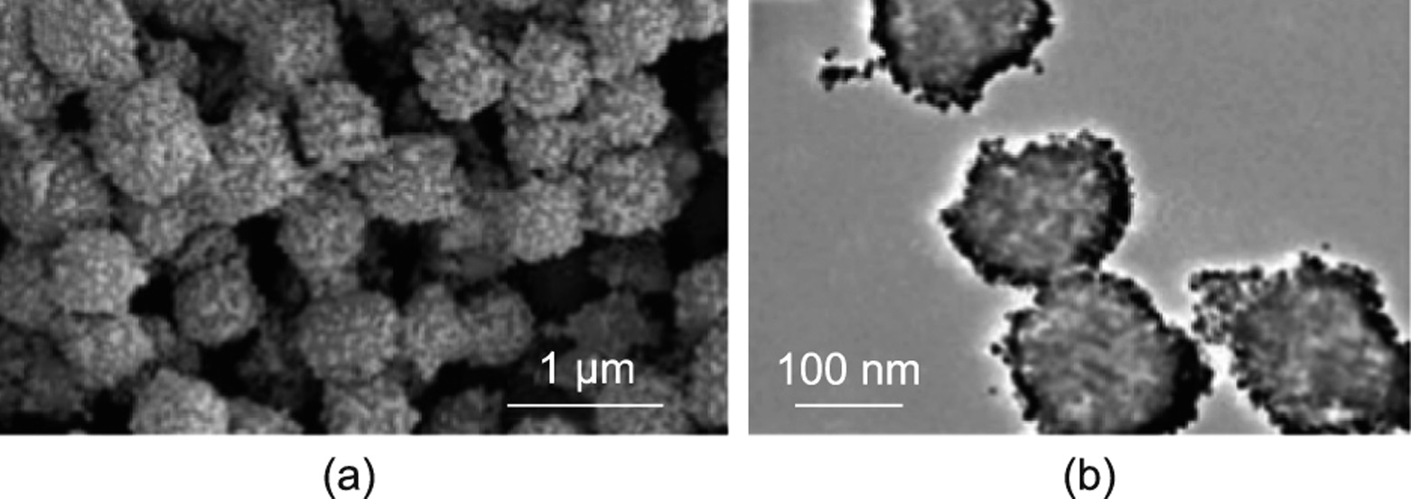
Fig. 10. (a) SEM image and (b) TEM image of poly(methylmethacrylate) (PMMA) @BaTiO3 particles. Reproduced from Ref. [116] with permission.
The continuous phase of EREs is generally a polymer with good elasticity to disperse solid particles. Compared to the dispersed particles, it possesses a much smaller dielectric constant and good insulation. A common dispersant is silicone rubber (e.g., PDMS [112–114]), and some studies have used gels (e.g., glycerin/gelatin [115,116]). As a dispersant, the mechanical properties of the elastic matrix without an electric field mainly determine the initial mechanical properties and applicable scenarios of EREs. Generally, a higher percentage increment of the mechanical properties can be obtained by using an elastic matrix with a lower elastic modulus [118], but other performance requirements should be considered in regard to selecting an elastic matrix.
Additives are the components used in the elastic matrix and filler to regulate the properties of the elastomer. Among the additives used in EREs, silicone oil is the most commonly used plasticizer. Adding silicon oil can ameliorate the dispersion state of the particles in the matrix, reduce the viscosity of the dispersion, and allow the particles to move more easily within the elastic matrix, which is conducive to the response of the ERE under an electric field.
《3.3. Mesoscopic structure of EREs》
3.3. Mesoscopic structure of EREs
EREs can be categorized as isotropic or anisotropic according to their particle distribution. The particles of isotropic EREs are uniformly and randomly distributed in the matrix. For anisotropic EREs, the particles are arranged in advance to be approximately parallel to the direction of the applied electric field during the curing process, and the structure remains this way after the matrix is cured.
The effect of the anisotropic mesoscopic structure of EREs on their ER performance has been investigated. Cao and Zhao [119] designed an ERE with a layered mesoscopic structure, proving that the anisotropic mesoscopic structure significantly affects the tunable stiffness of the ERE. The elastic deformation changes the direction of the mesoscopic structure, thus changing the electrostatic potential energy and producing adjustable stiffness under an applied electric field. Through theoretical calculations and numerical simulations (Fig. 11(a)) [119], they adjusted the thickness ratio Ht, dielectric constant ratio Hd, layered structure direction, and other parameters between the two media to obtain the maximum ER coefficient KER, corresponding to the highest adjustable stiffness under an electric field. PDMS was selected as the matrix and several other dielectric materials as the filler to calculate an adjustable modulus of more than 300 kPa in an electric field of 10 MV∙m–1 . The results indicate that the parallel layered mesoscopic structures have the highest ER coefficient. They also show that the parallel chain structure obtained by curing the EREs in an electric field is conducive to the improvement of the ER effect. Anisotropic EREs were successfully prepared and researched by Niu et al. [112] and Dong et al. [113]. They applied a direct current electric field in the curing process of EREs with a special mold. Fig. 11(b) [112] shows the device for curing the elastomer under an electric field. In addition to the direct current electric field, Kossi et al. [114] attempted to use an alternating current (AC) electric field while curing EREs. The results show that the ER properties of the samples cured under a direct current electric field are stronger than those cured with an AC electric field or no electric field. The above results show that anisotropic EREs possess stronger ER performance than isotropic EREs. In 2021, we used barium titanyl oxalate particles coated with urea nanoparticles (BTRU) and PDMS to prepare an anisotropic ERE with excellent performance. The highest relative ER effect is 17 160%, and the storage modulus increment is 5.2 MPa at 3 kV∙mm–1 . The performance of this ERE is currently the best among all EREs. The anisotropic structure can effectively form saturated surface polarization between particles by reducing the distance between particles along the direction of the electric field, and the electrostatic interaction between polarized particles in the electric field is effectively enhanced.
《Fig. 11》
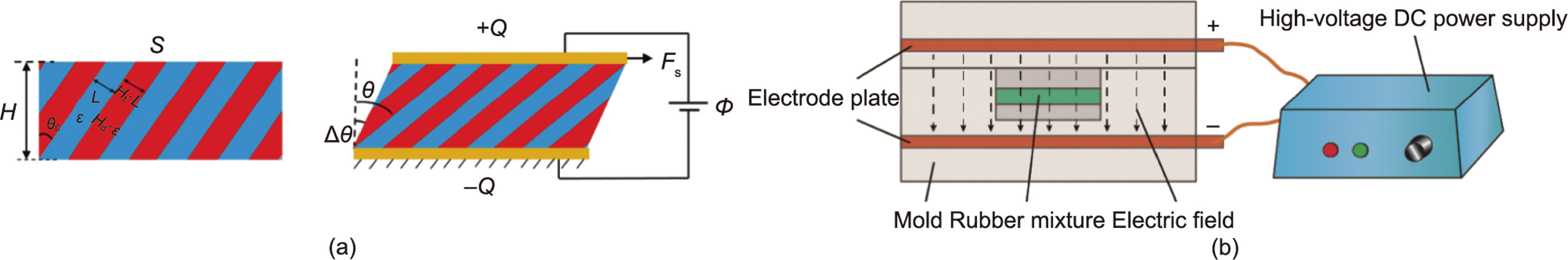
Fig. 11. (a) The layered structure of ERE when it is not deformed (left) and the structural change of ERE under the action of an external electric field and shear force (right). (b) Schematic diagram of the preparation of anisotropic ERE by applying a direct current electric field. Ht: the thickness ratio; Hd: dielectric constant ratio; A: surface area; H: thickness; Φ: external electrical voltage; Fs: shear force; △θ: shear strain; ±Q: charge on the surface; ε and Hd·ε are the permittivity of the two phases in the elastomer; L and Ht·L are the thicknesses of the two phases in the elastomer; θ0 and θ are the angles of ERE in different states. (a) Reproduced from Ref. [119] with permission; (b) reproduced from Ref. [112] with permission.
《3.4. Applications of EREs》
3.4. Applications of EREs
Due to the orientational polarization of particles in EREs with an external electric field, the shear modulus is significantly enhanced, and most applications of EREs are in shear mode; that is, the force direction is perpendicular to the particle interaction direction under an electric field. Biggerstaff and Kosmatka [120] were the first to use EREs based on silicone gel as a damper. Their research results showed that the stiffness of EREs could change to six times the initial value in the working state, and the damping factor could change to a third of the original value with an applied electric field. Wei et al. [121] designed ERE sandwich beams. By establishing a finite element model to predict the vibration response of the beam and through experimental analysis, it was concluded that the electric field intensity can effectively change the vibration characteristics of the beam, which can be applied to engineering structures. Koyanagi et al. [122] designed a linear actuator combined with an ER gel. After controlling the electric field intensity and adjusting the friction between the ER gel and the clutch, a maximum force of 10 N could be transferred. The linear actuator is applicable in the robotics field. Zhu et al. [123] designed a shear mode damper using EREs, as shown in Fig. 12(a). The rigidity and damping characteristics of the damper are regulated by applying an electric field to obtain a better damping effect. Ma et al. [124] also designed a shear mode damper using EREs, as shown in Fig. 12(b). The results show that the force–displacement hysteretic curve of the damper is tunable under an applied electric field and predictable via a proposed mechanical model. Yuan et al. [117] used EREs to adjust the amplitude of circular motion and designed the device, shown in Fig. 12(c). Under the alternating on/off electric field, the circular motion correspondingly generates the change of reduction and recovery, which demonstrates the feasibility of the application of the EREs in similar conditions. In addition, Zhou et al. [125] used high-performance anisotropic EREs to design and produce a smart table tennis racket with adjustable hardness (Fig. 12(d)). The racket can change the shooting angle and speed of the table tennis ball by adjusting the applied electric field, which is very suitable for table tennis players’ unconventional and adaptability training.
《Fig. 12》
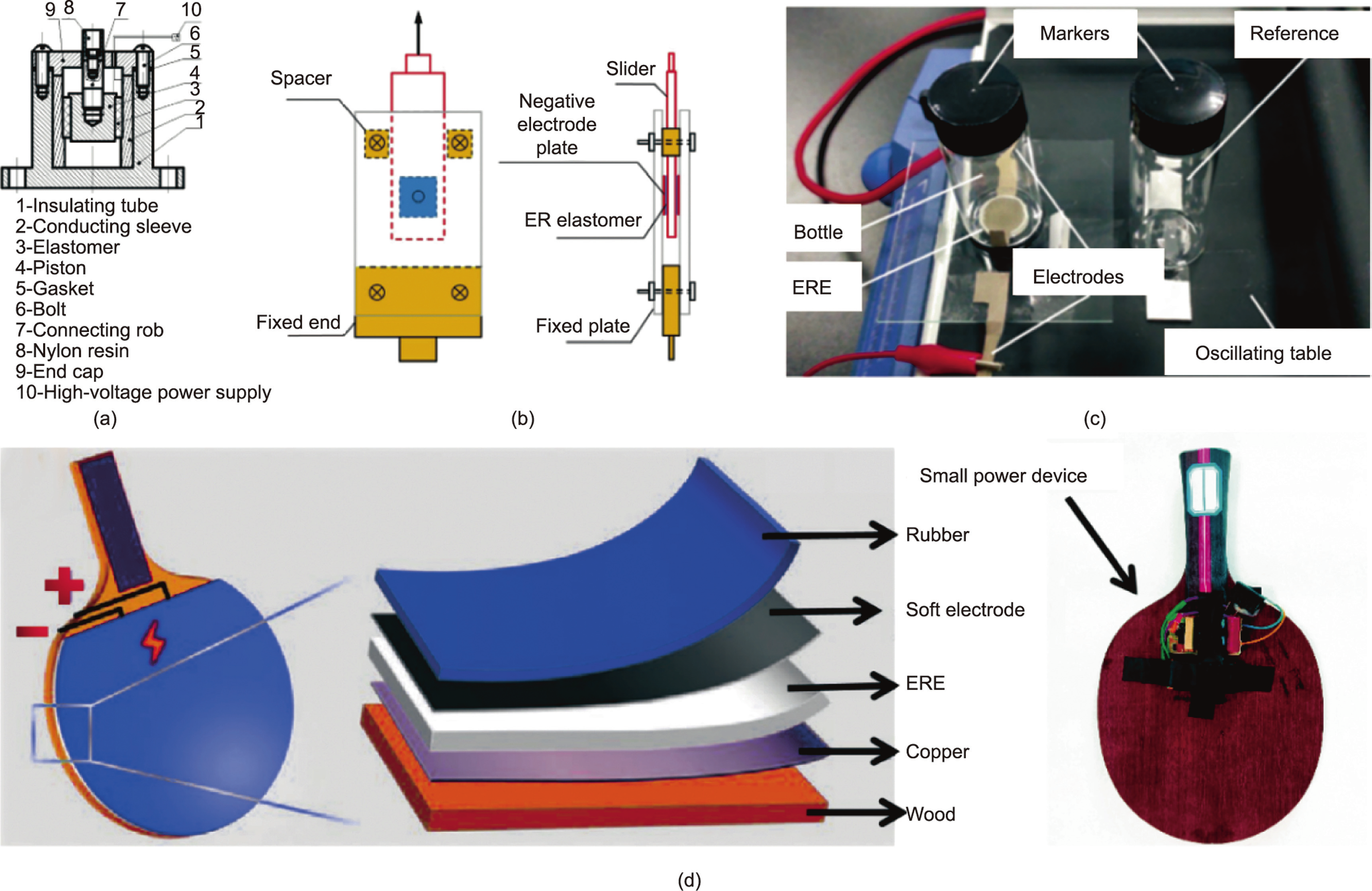
Fig. 12. (a) Structure diagram of the ERE shock absorber. (b) Structure diagram of the ERE shear mode damper. (c) Photograph of the device for adjusting the amplitude of circular motion [117]. (d) Schematic illustrations and structural design of smart table tennis rackets [125]. (a) Reproduced from Ref. [123] with permission; (b) reproduced from Ref. [124] with permission; (c) reproduced from Ref. [117] with permission.
According to these studies, EREs have been widely used in the shear mode, and the improvement and innovation of their damping device structure is a main development direction in the application field, but applications in compression mode are also worth studying.
《4. Applications of ER technology in other fields》
4. Applications of ER technology in other fields
Due to the unique characteristics of the ER effect, the dispersed phase forms a chain under the condition of an external electric field. Not only can the viscosity of the suspension be adjusted by adjusting the direction of the electric field, but the refractive index and conductivity of the system can also be changed. Therefore, the application range of ER technology is very wide. In addition to the common uses of ERFs and EREs, this technology can also be applied in many other fields, such as oil transportation [21], food processing [22], capacitors [25], energy technology [23], and new sensors [126].
《4.1. Viscosity reduction by ER technology》
4.1. Viscosity reduction by ER technology
The method of reducing fluid viscosity through ER technology was first used in crude oil transportation. In 2006, based on the ER effect, a new crude oil transportation method was proposed to reduce the viscosity of crude oil by applying an electric field in the direction of the crude oil flow, aiming to reduce transportation energy consumption and improve transportation efficiency [24,127]. Compared with the traditional heating method to transport crude oil, micro nanotechnology is not only suitable for various crude oils but also has extremely low energy consumption in low-temperature environments [21]. For example, when the ambient temperature is –3.1 °C, Tao et al. [21] used this technology to reduce the viscosity of a barrel of crude oil by 82.1%, consuming only 0.1025 kW∙h electricity. In addition, they also proved through neutron scattering experiments that the viscosity reduction in the direction of the electric field of crude oil is because the nanoparticles in the crude oil are arranged in chains along the direction of the electric field [21]. Similar to the equipment designed above, Du et al. [128] used an external electric field to reduce the apparent viscosity of diesel fuel containing sulfur nanoparticles, thereby increasing the degree of diesel atomization and ultimately achieving the improvement of combustion and engine efficiency.
The electric field directions used in the above studies are all parallel to the flow direction. To evaluate the correlation between the electric field direction and the effect of reducing the viscosity of crude oil, Huang et al. [129] changed the direction of the applied electric field to make the direction of the electric field perpendicular to the flow direction of a waxy crude oil. Under this condition, the rheological properties of the waxy crude oil with the change of the electric field intensity were tested. Under the action of an electric field whose direction is perpendicular to the direction of crude oil flow and whose electric field strength is 5 kV∙mm–1 , the viscosity of crude oil decreases by more than 80%. This proves that the viscosity reduction effect of waxy crude oil is not dependent on the direction of the electric field. Therefore, the decrease in the viscosity of waxy crude oil under the action of an external electric field cannot be simply attributed to the formation of a chain structure of dielectric components along the line of defense of crude oil flow [130]. They speculated from the change in the conductivity of crude oil with or without an external electric field that the interfacial polarization of wax particles should be the main mechanism of the rheological behavior of waxy oil. Specifically, for waxy crude oil systems, wax particles have a huge impact on the viscosity of crude oil, which is related not only to the viscosity of the waxy components but also to the interaction and structure between them. When an electric field is applied, the dotted particles in the waxy crude oil system will accumulate on the surface of the wax particles to form larger agglomerates, and under the action of electrostatic repulsion, the van der Waals force between the particles in the crude oil system can be reduced. The reduction of the structural strength of crude oil is macroscopically manifested as a reduction in viscosity [131,132]. This method of reducing the viscosity of crude oil has a certain time effect. In addition, the type of crude oil and ambient temperature will also have a certain influence on the viscosity reduction effect. Although this method has excellent prospects for large-scale industrial application, it is necessary to apply the method to actual crude oil transportation in the future, which requires specific analysis of the type of crude oil and the timing of applying an electric field (location, temperature, etc.).
In addition to crude oil transportation, the method of reducing fluid viscosity through ER technology has also been used in the field of food processing, such as reducing the fat content in chocolate through this method. Although chocolate is a delicious food and is loved by many people, unfortunately, chocolate products contain a large amount of fat, which is bad for health and can easily lead to obesity. This problem has been studied for many years, but there is no suitable way to reduce the fat content of chocolate. This is mainly because the melted fat acts as a continuous phase in the production of chocolate, so that the particles of cocoa, sugar, milk solids, and so on, are uniformly dispersed. If the fat content is reduced, melted chocolate will not be produced due to its high viscosity. Based on the ER effect, Tao et al. [133] uses an external electric field to reduce the viscosity of the molten chocolate, thereby making it possible to reduce the fat in the chocolate. An electric field is applied along the flow direction of the liquid chocolate to gather the cocoa powder particles into micron-sized rectangular spheres (Fig. 13(a)) [21,133]. This change in microstructure disrupts the rotational symmetry and reduces the viscosity of the melted chocolate in the flow direction. In this way, a 10%–20% reduction in chocolate fat content is achieved. This method of reducing the viscosity during the processing of certain foods using the ER effect is universal and can be achieved by simple equipment. Therefore, it has broad application prospects in the food industry.
《Fig. 13》
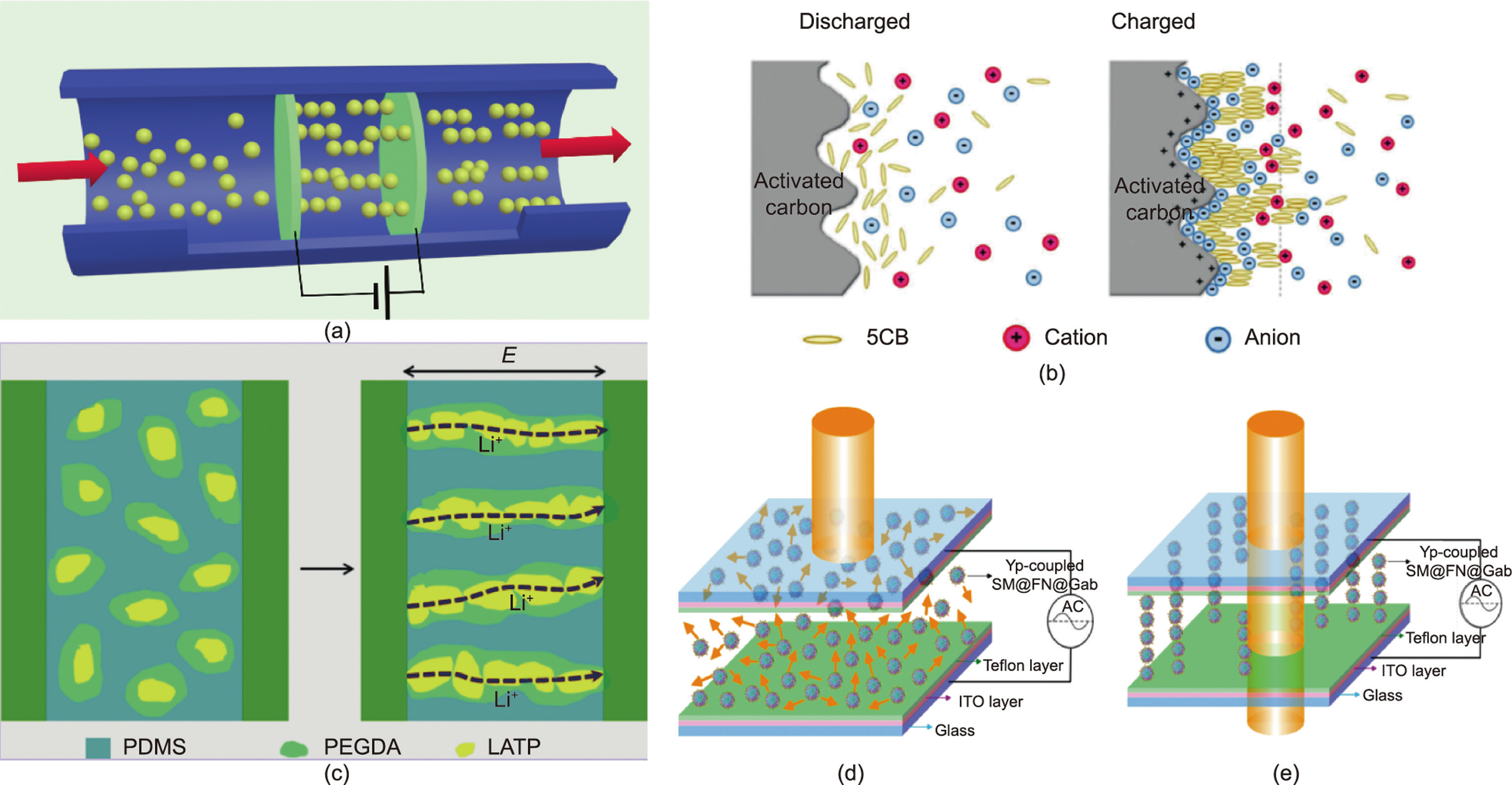
Fig. 13. (a) Schematic diagram of reducing crude oil or chocolate viscosity by applying an electric field [21,133]. (b) Schematic diagram of the principle of a nematic liquid crystal 4-n-pentyl-4' -cyanobiphenyl (5CB) increasing fluid viscosity in a capacitor electrolyte. (c) Schematic diagram of the parallel alignment of the electric field of LATP@PEGDA. LATP: Li1.3Al0.3Ti1.7(PO4)3; PEGDA: poly(ethylene glycol) diacrylate. Schematic diagram of the microscopic arrangement of particles in an ED without (d) or with (e) an alternating electric field [126]. SM: polystyrene microsphere; FN: magnetic nanoparticle; Yp: Yersinia pestis; Gab: protein G. (b) Reproduced from Ref. [25] with permission; (c) reproduced from Ref. [23] with permission; (d, e) reproduced from Ref. [126] with permission.
《4.2. Viscosity improvement by ER technology》
4.2. Viscosity improvement by ER technology
Supercapacitors are different from traditional chemical power supplies. They are power supplies with special performance that lies between traditional capacitors and batteries. Supercapacitors mainly rely on electric double layers and redox pseudocapacitors to store electrical energy. They not only have the fast charging and discharging characteristics of capacitors but also have the energy storage characteristics of a battery [134]. However, the main limitation to the application of supercapacitors is the shortterm energy storage caused by self-discharging that further induces loss of stored energy. Xia et al. [25] added the nematic liquid crystal 4-n-pentyl-4' -cyanobiphenyl (5CB) to the electrolyte of supercapacitors, using the ER effect of 5CB to reduce leakage and suppress self-discharge. When a capacitor is charged, the 5CB molecules are forced to move and gather under the action of an electric field to form an oriented arrangement along the direction of the electric field (Fig. 13(b)) [25]. The fluid viscosity, which is tunable through the external electric field, can be enormously enhanced with the transformation of the molecular order. When the capacitor is charged, the viscosity of the fluid in the capacitor will increase, which will hinder the reduction of ion diffusibility, resulting in a reduction in leakage current and suppression of self-discharge. Consequently, the charge redistribution and faradaic reaction, as two main processes of self-discharging, can be effectively restrained.
《4.3. Electric-field-oriented all-solid-state lithium-ion batteries》
4.3. Electric-field-oriented all-solid-state lithium-ion batteries
Solid ceramic polymer electrolytes with excellent performance have become attractive materials [135]. Generally, the preparation process of solid polymer electrolytes is complicated and cumbersome. The traditional solution casting method consumes organic solvents, and the solventless hot pressing method consumes energy [136]. Therefore, the preparation of high-performance solid electrolyte polymers has a huge impact on the energy sector. Liu et al. [23] proposed a simple strategy for the arrangement and assembly of inorganic particles via an external AC electric field. They used the ER effect to make the ceramic particles distribute along the direction of the electric field under the action of an external electric field during the preparation of the solid ceramic polymer electrolyte. After the polymer was solidified, a directionally assembled solid ceramic polymer electrolyte was obtained. Through the action of an external electric field, an aligned ion conduction network path is formed in Li1.3Al0.3Ti1.7(PO4)3 particles and poly(ethylene glycol) diacrylate (LATP@PEGDA), thereby promoting the movement of ions and improving the ion conductivity (Fig. 13(c)) [23]. Based on the ER effect, through the simple strategy of applying an external electric field during the preparation process, the ceramic particles in the composite electrolyte can be aligned to form an efficient 3D lithium-ion conductive network, which is of great significance for the development of highperformance solid electrolytes.
《4.4. Sensor applications》
4.4. Sensor applications
ER sensors can quickly and visually diagnose diseases based on changes in the transmittance of an ERF under an applied electric field. Chou et al. [127] described an ER sensor for plague diagnosis with rapid visualization. They first coated polystyrene microspheres (SMs) with magnetic nanoparticles (FNs) to prepare core–shell structured microspheres SM@FN, and then coated the anti-Yersinia pestis (Y. pestis, Yp) antibody (ab-YP) on SM@FN as a biosensing medium. Two indium tin oxide glass pieces with a spacer were used to form an ER display (ED) to hold the ab-YPmodified microsphere solutions and observe the change in transmittance. The ED encapsulating the dispersed SM@FN solution is opaque (Fig. 13(d)) [126]. Under the application of an alternating electric field, based on the ER effect, the particles will be arranged in the direction of the electric field, thereby changing the transmittance of the ED (Fig. 13(e)). The frequency when the transmissivity reaches the maximum value is defined as the characteristic frequency ( ). can be used as a signal of the shell material. When the plague antigen was coupled with the specific antibody on the particle, the Fc of the particle changed from 200 to 750 kHz. The great changes in ED transmittance could be used to diagnose Y. pestis without fluorescence labeling. When the antigen concentration was more than 30 and 40 ng·μL–1 , it could be detected in 30 s. Compared with other commonly used immunoassay methods (including secondary immunochemistry or enzyme-linked methods), this simple, extremely sensitive and highly selective ER sensor was expected to become a candidate method for field diagnosis of plague.
《5. Summary and outlook》
5. Summary and outlook
Based on the theory of ER technology and combined with the latest research results, as shown in Figs. 14 [6,8,14,16–18,20,23– 25,28,29,33,34,44,46,56,64–67,72,73,78–82,84,85,88,91,94,97–99, 107–109,112,113,115–117,120,121,126,129,133], this paper presents the recent research progress and related applications of ER materials. The introduction of materials is classified and summarized according to the main components of the materials, and the main methods to improve the performance of ER materials are described. The application section mainly introduces the applications of ER technology in other fields, which is also a good development direction of ER technology in the future. For the research and development of ERF materials, the focus is on the investigation of their dispersed phase because the material type, dielectric and conductive properties, particle size, particle volume fraction, and so on, of the dispersed phase play a vital role in the performance of the ERF. In recent years, researchers have discovered that the structure and geometry of particles have a huge impact on the ERF. In particular, the performance of particle-type ERFs with hollow structures and rod-like geometries far exceeds that of spherical particle-type ERFs. Therefore, research on the particle size and morphology of the dispersed phase of ERFs has also become a research hotspot. The study of the continuous phase of ERFs is also crucial. GERF with a binary liquid phase through the addition of alkane into the silicone oil continuous phase may provide a new direction to improve the comprehensive performance. The ER efficiency of GERFs with a binary liquid phase reaches 10 656, and its viscosity is extremely low, while its stability is still excellent.
《Fig. 14》

Fig. 14. Based on the development history of ER technology theory, this article mainly introduces the development diagram of ER materials and applications.
In addition, the research progress in EREs in recent years is being reviewed, the compositions, mechanisms, and applications of EREs are introduced, and the methods and directions for improving the performance of EREs from recent studies are summarized. One of the important targets is to improve the application performance, namely, the storage modulus increment and the relative ER effect, which are mainly related to the properties of particles. A polar molecular layer, surface modifications, an asymmetric shape, and a core–shell structure of particles can be used to improve the ER effect of EREs by curing the ERE under an electric field. If these methods are improved or combined, then EREs with better performance can be obtained.
Two common indicators to evaluate the ER performance of an ERE are the storage modulus increment and the relative ER effect. Many other properties, such as the service life and creep properties, need to be tested when EREs are used in real life. The development history of EREs is not as long as that of ERFs, and thus, the complicated interaction between particles and the interaction between particles and the matrix are not as clearly understood and need to be discussed. EREs have the advantages of a tunable stiffness with an applied electric field, without problems such as agglomeration and leakage, and they are easier to design than ERFs. The shear mode is widely used in applications, so better structural design and pioneering use modes of ERE devices are worth researching.
The ER effect and technology have been discovered and developed for more than 80 years and the performance of ER materials has been continuously improved. At same time, their applications and devices have been demonstrated and expanded. For example, in the field of ER intelligent dampers, there is a commercial application demonstration, and in the energy field, there is a demonstration of crude oil transportation. However, these currently application results only remain at the level of application demonstration and have not yet been applied on a large scale. In terms of materials, the stability, temperature adaptability, and abrasion resistance of ER materials have restricted their application in the engineering field. For practical engineering applications, the encapsulation of ER materials, the applicability of electrodes during use, and the selection of device materials are all difficulties remaining to be solved. In addition, the reasons for restricted application are not only due to some performance shortcomings of ER materials and immature application technology but also related to application positioning and development. Therefore, ER materials database including the synthesis, compositions, properties, performance, and application data could be established. The research and development of new materials or materials with certain advantages should be guided by practical applications and these processes could be accelerated by artificial intelligence-based computational technology such as data mining. If there is a lack of reasonable application positioning and development, then undirected research and development of new materials will cause unnecessary waste. Therefore, to develop ER technology and expand its application, more resources need to be invested in application positioning and development.
《Acknowledgments》
Acknowledgments
The authors are grateful for financial support the Key Research Project of Zhejiang Laboratory (No. 2021PE0AC02) and the National Natural Science Foundation of China (11704239, 61922053, and 11674210).
《Compliance with ethics guidelines》
Compliance with ethics guidelines
Yudai Liang, Dongyang Huang, Xuefeng Zhou, Ziqiu Wang, Quan Shi, Yaying Hong, Huayan Pu, Mengying Zhang, Jinbo Wu, and Weijia Wen declare that they have no conflict of interest or financial conflicts to disclose.


 京公网安备 11010502051620号


