

《1.Introduction》
1.Introduction
Inconel 718 (IN718) is a well-known nickel-based superalloy that is extensively used in high-value-added engineering applications such as jet engines in aerospace and steam generators in nuclear power plants, as well as in the defense and marine sectors, due to its excellent mechanical properties, fatigue resistance, and corrosion resistance [1–4]. This material has a relatively medium hardness but becomes hardened when subjected to work. The traditional fabrication method is through vacuum induction melting and high-precision machining [5]. However, the machining of Inconel is a major challenge because the cutter wears down quickly due to the work-hardening effect, in which Inconel becomes hardened after a few layers of material removal.
Additive manufacturing (AM), also known as three-dimensional (3D) printing, forms a part layer by layer, and is thus the best solution to fabricate a near-net-shape component made of Inconel materials with minimal post treatment or without post machining [6–8]. On the one hand, the printing process parameters, such as laser power, scanning speed, powder layer thickness, and hatch spacing, play a vital role in producing a dense part [9–12]. On the other hand, raw Inconel powder has considerable influence on the printing process and on the quality of the parts. A literature search reveals that a considerable amount of work has been done thus far on process optimization to print Inconel powders successfully; however, a limited amount of research has been carried out to study powder characteristics, and particularly those of Inconel powder, for AM [13,14].
The present study presents insights into the characteristics and behaviors of IN718 powder for AM, and pays particular attention to the particle shape, particle size distribution (PSD), surface texture, rheological or flow characteristics, and packing behavior of the Inconel powder.
《2.Experimental procedures》
2.Experimental procedures
A virgin IN718 powder with the chemical composition shown in Table 1 was used in this study. After 10 repetitions of printing cycles,the recycled powder was sampled to observe its changes as compared with the virgin powder.
《Table 1》
Table 1 Chemical composition of virgin and recycled IN718 powders.

These powders were characterized using various powder characterization techniques and equipment, such as a laser particle size analyzer HORIBA LA-960, a Hall flowmeter, a nominal density cup, a tapping apparatus, an FT4 powder rheometer, and a field emission scanning electron microscope (FESEM). In addition, an EOS-M400 selective laser melting (SLM) system was used to print the demonstration samples.
《2.1. Particle size analyzer》
2.1. Particle size analyzer
A HORIBA LA-960 laser particle size analyzer was used in accordance with the ISO 13320-1 standard to quantify the particle size, PSD, and particle fraction at specific particle sizes using the laser-scattering technique. A small quantity of each IN718 powder sample, with a refractive index of 1.958, was poured into deionized water with a refractive index of 1.333. The powders were mechanically and ultrasonically stirred, circulated, and degassed before measurement. Five consecutive readings were taken in the automatic mode and five measurements were carried out in the manual mode to confirm the consistency of the results. The results are shown in Table 2.
《Table 2》
Table 2 PSD and Hall flow rate of virgin and recycled IN718 powders.

”D10 ”, “D50 ”, and “D90 ” mean the particle sizes at 10 vol%, 50 vol%, and 90 vol%, respectively.
《2.2. Microscopy analysis》
2.2. Microscopy analysis
A FESEM was used to examine the shape, size distribution, surface morphology, surface texture, and satellite effects of the IN718 powders. In addition, optical microscopy was employed to observe the internal porosity, defects, and cross-section of the powders. The results are presented in Fig. 1 and Fig. 2.
《Fig. 1》

Fig. 1. Cross-section of (a) virgin and (b) recycled IN718 powders.
《Fig. 2》

Fig. 2. PSD and surface morphology of (a) virgin and (b) recycled IN718 powders.
《2.3. Flow rate measurement using a Hall flowmeter》
2.3. Flow rate measurement using a Hall flowmeter
The Hall flow rate of these powders was measured in accordance with the ASTM B213 standard test method. A 50 g mass of each powder was weighed to an accuracy of 0.0001 g and gently poured into the Hall flowmeter funnel. The discharge orifice at the bottom of the funnel was then unlocked to let the powder flow naturally. A timing device was started simultaneously to record the flow duration. Five measurements using virgin powders were carried out; these values were taken into average and the results are shown in Table 2.
《2.4. Rheological measurement》
2.4. Rheological measurement
To date, the FT4 powder rheometer is the most powerful universal powder tester to quantitatively measure a powder’s resistance to flow while it is in motion. Different conditions such as stability, variable flow rate, tapped condition, compressibility (CPS), aeration, permeability, and wall friction can be performed. In the present study, the stability and variable flow rate modes were carried out. The basic flow energy (BFE), stability index (SI), flow rate index (FRI), specific energy (SE), and conditioned bulk density (CBD) were obtained, and are presented in Table 3 and Fig. 3.
《Table 3》
Table 3 Rheological results of virgin and recycled IN718 powders.

CPS: compressibility; UYS: unconfined yield strength; MPS: major principle stress; FF: flow function; AIF: angle of internal friction; WFA: wall friction angle.
《Fig. 3》
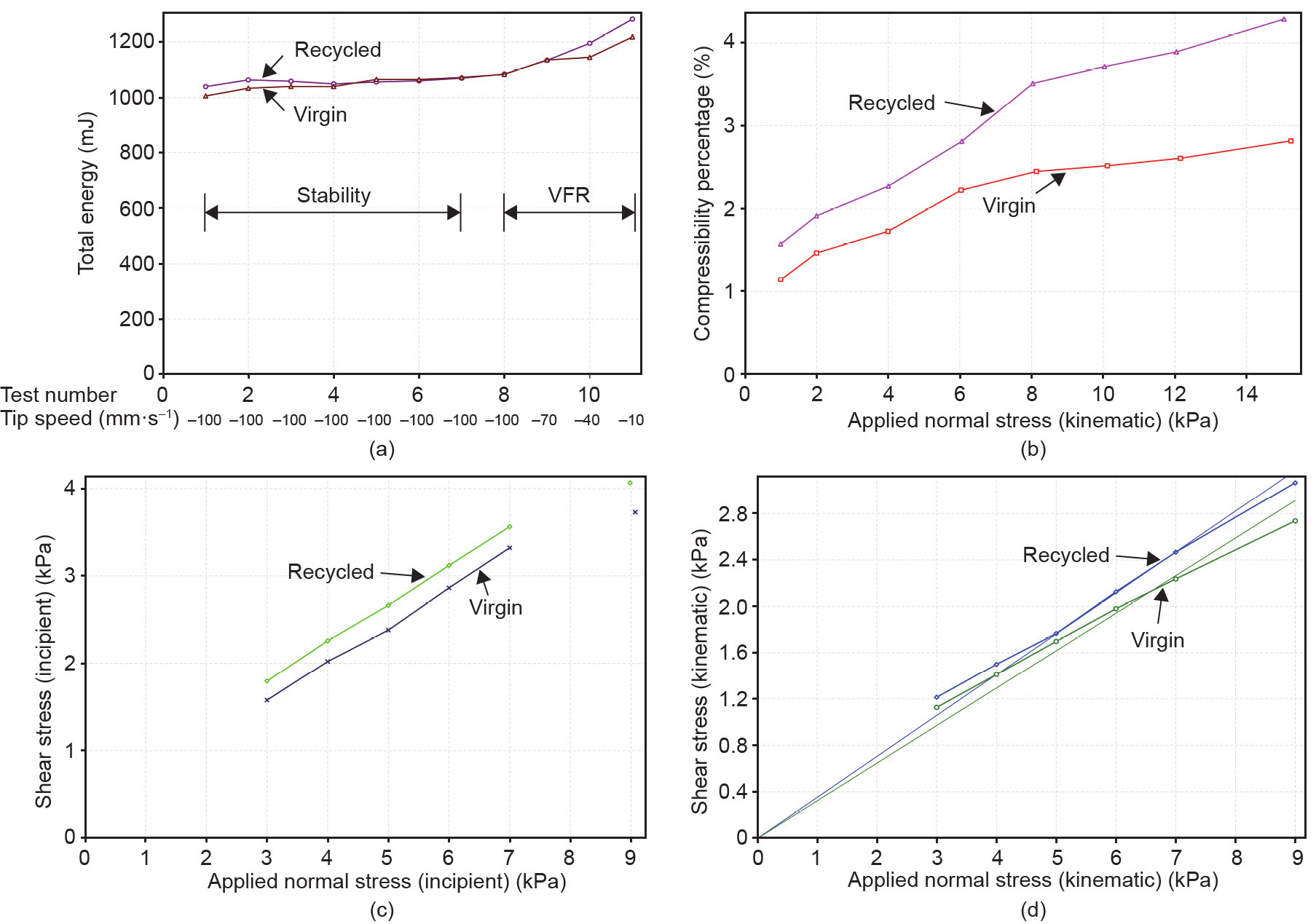
Fig. 3. The results of rheological tests for virgin and recycled IN718 powders. (a) Stability and variable flow rate (VFR) test; (b) CPS test; (c) shear test; (d) wall friction test.
《2.5. Apparent, tapped, and true densities》
2.5. Apparent, tapped, and true densities
Apparent density was measured according to the ASTM B212 standard. A nominal density cup of 25 cm3 was placed under the Hall flowmeter funnel. The powder was subsequently poured into the funnel such that it flowed down and filled the cup completely. A non-magnetic blade was used to level off the powder with the top of the cup. The weight of the powder inside the cup over the nominal volume (25 cm3) provides the apparent density of the powder. The experiments were repeated five times to ensure consistency.
A tapping apparatus was used to measure the tapped density in accordance with the ASTM B527 standard. The powder was weighed and poured into a graduated cylinder. A total of 3000 taps were conducted with a tapping frequency of 300 taps·min–1. The average volume between the highest and lowest readings on the graduated cylinder was taken as the tapped volume of the powder. Five measurements were carried out with the virgin powder, and the average value was determined.
An AccuPyc II 1340 gas displacement pycnometry system was used to measure the true density of the powders according to the ASTM B923 standard. The powder was weighed and poured inside a calibrated aluminum cylinder (10 cm3). Helium gas was used as a displacement medium, as it is able to penetrate into the very small gaps between powder particles. The difference in pressure before and after the gas expansion was measured to calculate the volume of the powder. Each powder sample was measured 20 times to ensure the accuracy of the measurement. The results are presented in Table 4.
《Table 4》
Table 4 Results of apparent, tapped, and true densities, and packing capability of virgin and recycled IN718 powders.

aThis result was calculated after 3000 taps.
《2.6. Selective laser melting (EOS-M400)》
2.6. Selective laser melting (EOS-M400)
An EOS-M400 SLM machine with a build size of 400 mm × 400 mm × 400 mm and laser power of up to 1 kW was used to build the typical tensile coupons and a propeller using the current powder. A strike-scanning strategy and process parameters including a laser power of 300 W, a scanning speed of 1500 mm·s–1, hatch spacing of 55 m, and a layer thickness of 40 m were employed. Fig. 4 provides an image of the printed propeller, and Fig. 5 shows the tensile property and typical microstructure.
《Fig. 4》

Fig. 4. A propeller printed using the EOS-M400 machine.
《Fig. 5》

Fig. 5. Typical microstructure of IN718. (a) 3D view; (b) higher magnification showing column structure in XZ plane.
《2.7. Tensile test》
2.7. Tensile test
Standard heat treatment was performed on the tensile samples according to AMS 5664 specifications. Solution heat treatment (i.e., heated at 1040 ℃ for 2 h and then cooled in air) was followed by precipitation hardening treatments (i.e., aged at 720 ℃ for 8 h and then cooled to 620 ℃ for 8 h) [15]. Finally, a tensile test was performed using an Instron 5982 testing machine equipped with an automated video extensometer and a strain rate of 10–4 s–1 in accordance with the ASTM E8 standard.
《3.Results and discussion》
3.Results and discussion
《3.1. Particle size distribution》
3.1. Particle size distribution
It is very important to know the PSD, as different AM techniques have their own requirements. For example, SLM currently uses powders with particle sizes ranging from 15 µm to 63 µm, while the PSD for electron beam melting (EBM) varies from 45 µm to 105 µm, due to technical challenges such as smoking and sparking effects [7,9].
Table 2 presents the results of the PSD of different Inconel powder samples using a HORIBA LA-960 laser particle size analyzer, according to the ISO 13320-1 standard. In addition, Fig. 1 and Fig. 2 show the internal defect and morphology of the powders, respectively. In practice, after gas atomization, the powders would be sieved to the different size ranges for different applications such as micro-metal injection molding (micro-MIM), thermal spray, and AM [16].
As shown in Table 2, the mean particle size (D50) for SLM applications is about 31 µm. PSD has a direct effect on the quality of a 3D built part, and particularly on the surface finishing of the printed parts. A lower average particle size results in better surface roughness of the printed parts. Fig. 4 shows a built part made from our inhouse SLM machine using the IN718 powder. The SLM-built part’s finishing surface is visibly very smooth, with a surface roughness value of (7.447 ± 1.683) µm. The mean particle size, D50, is not the only factor to affect the quality of built parts; the range of particles also plays a role. A wide PSD leads to an uneven spread layer, and creates high surface roughness of the printed part. Spierings et al. [17] carried out experiments with a narrow PSD (7.12–24.17 µm, 19.84–41.13 µm, and 15.26–55.54 µm) and observed significant improvements in both mechanical properties and finishing surface for the sample with the lowest PSD.
It was observed during the printing process that if the PSD is too large, the laser power is unable to melt the largest particle completely, or will over-melt the small particles, leading to spatter/unmelted particle/pore and balling/swelling effects. In addition, it was experimentally noted that too-small powder particles (i.e., less than a few microns) flew up along the vortex turbulence due to the inert gas flow during the SLM printing process [8]. It is therefore advised that the PSD for an SLM method should range from 15 µm to 63 µm, or fall within an even smaller range.
《3.2. Flowability of AM powder》
3.2. Flowability of AM powder
Flowability is an important parameter for powders in AM because it simulates what happens during the powder-raking process. Among the various shapes of powder particles (irregular, angular, and spherical), only spherical-shaped particles can provide the highest flowability, as the particles of such powders have minimal contact areas with neighboring powder particles, thus creating less internal friction force and requiring the minimal raking force in order to flow [18].
Table 2 shows the Hall flow rate of virgin and recycled powders according to the ASTM B213 standard. The recycled powders had a slightly lower flow rate of 29.47 s·(50 g)–1, compared with the flow rate of 28.35 s·(50 g)–1 for the virgin IN718 powder. This is because the recycled powder particles became slightly deformed over time and were no longer spherical in shape. Some of the recycled powders also tended to stick together (Fig. 2). In addition, recycled powders may come into contact with moisture during the powder-recovery process, for example, due to blasting, sieving, storage, and reloading processes. High moisture, which can rise to 90% in a tropical environment, is of great concern in a powder’s characteristics. It strongly affects a powder’s flow behavior during the powder-raking process, and thus results in negative effects on the printing parts. In this study, the powders were always stored in a moisture-controlled dry cabinet with a moisture content that was constantly maintained at 23%. In addition, it would definitely be beneficial to bake the powders in a vacuum oven before carrying out the tests [8].
Rheological tests were carried out to determine the stability and variable flow rate, CPS, shear, and wall friction of the virgin and recycled powders; the results are summarized in Table 3 and Fig. 3 [19]. In general, the virgin powder had better rheological properties (flow characteristics) than the recycled powder as compared over four different tests—namely, the stability and variable flow rate, CPS, shear, and wall friction tests. It was observed that both the virgin and recycled powders were practically stable in a seven-cycle test, as seen in the stability region in Fig. 3(a), and had an SI close to 1, as shown in Table 3.
In addition, the results of the BFE and/or SE tests revealed that a much higher energy was required to move the virgin and recycled powders (1032 mJ and 1091 mJ, respectively). Lighter powders such as aluminum alloy powders require less energy (about 150 mJ) to move than these heavier powders. Moreover, the variable flow rate simulates what happens during the powder-raking process, when there is a change in the raking speed. The results of the FRI indicate that more energy was required to move the powders when the raking speed was lower.
Table 3 and Fig. 3 also show that the recycled IN718 powder has a much higher CPS percentage (4.3%) than the virgin powder (2.8%). This indicates that some of the virgin powders adjacent to the melt tracks were re-melted and deformed during the printing process (Fig. 2). A higher CPS percentage would affect the density and quality of printed parts. This result was further confirmed in the shear and wall friction tests, as the deformed powders needed more energy to move against each other, and caused higher friction against the blade [19].
《3.3. Powder density and packing capability》
3.3. Powder density and packing capability
Some AM powders flow easily while others flow less easily; however, the way in which the powder particles are tightly packed together during the powder-raking process is also of the utmost importance for AM, in order to achieve dense built parts. There are several ways to measure the density of powder; in particular, these methods include measuring the apparent density, tapped density, true density, and powder-bed density. The apparent density simulates the loosing packing state of powder, and is measured according to the ASTM B212 standard. The tapped density demonstrates the self-powder stress-packing state, whereby powder particles sit tightly together after a number of taps; it is measured according to the ASTM B527 standard. The true density expresses the bulk density of a powder, and is measured using a pycnometer according to the ASTM B923 standard. The most practical way to measure the density of a metallic powder in AM is the powder-bed density. Although a few researchers have attempted to study powder-bed density, no standard exists for this measurement as yet [20,21]. The challenges are: ① to determine the actual layer density during the printing process; and ② to determine how to optimize the relevant AM processing parameters in order to achieve the highest powder packing and obtain higher quality built parts.
Table 4 presents the density results of virgin and recycled IN718 powders. It was observed that the apparent and tapped densities of the virgin powder are relatively higher than those of the powder that was recycled 10 times; again, this result is due to the effect of deformed spherical particles after recycling. However, the true density of the recycled powder was slightly higher than that of the virgin powder because particles with pore defects had been re-melted, and the entrapped gas had subsequently been removed. It is well established that spherical particles have the highest packing density as compared with other forms of particles [22]. Bigger particles have a higher packing capacity than small ones due to the relative contribution of gravity versus the particle-particle forces. Particles with a wider PSD have a better packing ability than those with a narrower PSD.
A literature search revealed that different powder-bed fusion machines, such as Arcam, EOS, Concept Laser, and 3D Systems, used different powder-spreading techniques, which resulted in different powder-bed densities. The current powder-packing density using soft or hard coaters is 47%–55%, which is similar to the packing capacity at the apparent density (see Table 4) [4,7]. Other 3D printing machines use a roller technique to spread and compress the powder, which is claimed to achieve better powder-bed density and higher quality built components. It is also true that the building time would be significantly shorter if the powder-bed density was improved (from 47%–55% to close to packing capacity at a tapped density of 60%–65%, which accounts for 20%–30% density improvement).
《3.4. Tensile property》
3.4. Tensile property
Tensile coupons were printed and a universal Instron 5982 testing machine was used to carry out the test on the heat-treated tensile bars. Table 5 presents the mechanical properties of parts printed using virgin and recycled powders, including an average microhardness of 325 HV, a yield tensile strength (YTS) of 1210 MPa, an ultimate tensile strength (UTS) of 1404 MPa, and an elongation of 18.5% for the parts built using virgin powder. It is clear that the mechanical properties produced by AM superseded those produced via traditional methods [5]. This is because a very fine microstructure (Fig. 5) was achieved due to the super-cooling effect (about 107 ℃·s–1). It is also notable that when the chemical composition of the recycled powder was analyzed, the variation between the virgin powder and the recycled powder was found to be negligible (Table 1). An insignificant slip in mechanical properties was observed when the virgin powder was recycled a number of times, as long as the recycled powder was sieved well and stored in a humidity-controlled environment [8].
《Table 5》
Table 5 Mechanical properties of parts printed using the virgin and recycled IN718 powders.

《4. Conclusions》
4. Conclusions
AM is an emerging technology that will challenge current design limitations and open up a new way of fabricating components with complex features. The powder input must pass stringent criteria in order to meet the printing quality, dimensional accuracy, and finishing surface requirements, particularly in terms of chemical composition and powder PSD, shape, flow characteristics, and packing capability. The current IN718 powder is generally acceptable for 3D printing. It is shown that the powder can be recycled for use with proper handling, sieving, and storage. However, further optimization of the gas atomization process is essential in order to obtain more spherical particles and less satellite powder to promote better flowability and packing capability.
《Acknowledgements》
Acknowledgements
The authors acknowledge the financial support provided by A*STAR Additive Manufacturing Centre (AMC) Initiative: Work package 1—High temperature materials development for 3D additive manufacturing (142680088).
《Compliance with ethics guidelines》
Compliance with ethics guidelines
Quy Bau Nguyen, Mui Ling Sharon Nai, Zhiguang Zhu, Chen-Nan Sun, Jun Wei, and Wei Zhou declare that they have no conflict of interest or financial conflicts to disclose.


 京公网安备 11010502051620号


