

《1. Introduction》
1. Introduction
At present, flight vehicle structure maintenance is undergoing a paradigm shift from preventive maintenance depending on calendar time and flight cycle to condition-based maintenance (CBM) using structural condition monitoring data. This shift is driven by the need to better ensure the structural integrity, functionality, safety, and reliability of a flight vehicle during its life cycle, as well as to reduce the system maintenance cost. It provides an opportunity for the application of structural health monitoring (SHM) technology in flight vehicles [1–3].
An important basic condition of CBM is SHM, which integrates a sensor network into the structure and evaluates its state and integrity by analyzing and processing the signals collected by the sensor network. The main types of monitoring parameters include structural strain, vibration, temperature, and other physical quantities, as well as various defects and damages. Among them, deformation monitoring is an important part of a flight vehicle’s SHM [4–6]. During the life cycle of a flight vehicle, it is essential to conduct real-time monitoring of structural deformation using effective technical methods and devices to ensure its structural performance, safety, and reliability, as well as to predict the remaining service life. Such monitoring can also significantly reduce the cost of inspection and maintenance.
Optical fiber sensing (OFS) technology is regarded as one of the most promising technologies among various monitoring methods. Using optical fibers as the medium and combining optical signal transmission with sensing and measurement, this technology acquires various types of physical information such as the strain, displacement, acceleration, and temperature of the test structure by demodulating the changes in optical frequency, phase, amplitude, and polarization state. This paper focuses on OFS technology, which has attracted a significant amount of attention and has been studied extensively in recent years. We review and analyze the development history, technology varieties, reconstruction algorithms, and applications of structural deformation monitoring technology, point out the key unresolved problems, and present future development directions.
《2. Development history》
2. Development history
《2.1. Deformation classification and types of monitoring parameters》
2.1. Deformation classification and types of monitoring parameters
A flight vehicle structure experiences various kinds of deformation during its manufacturing and service processes, which can be categorized into passive and functional deformations. Passive deformations occur when the structure is subject to the action of a load. These can be further divided into quasi-static and dynamic deformations. Quasi-static deformations include micro strain deformation, thermal deformation, residual deformation, and so forth, which occur when a structure is subject to the actions of aerodynamic force, impact, vibration, thermal radiation, and so on. Dynamic deformations occur when a structure is subject to the actions of flutter, impact, and so on. Functional deformations refer to spatial deformations of telescopic mechanisms such as the satellite solar array, and of morphable structures such as the wings of the morphing aircraft. The main parameters involved in deformation monitoring include the strain, displacement, and acceleration of specific points along a specific direction, as well as the strain field and overall displacement of the structural surface.
《2.2. Development status of deformation-monitoring technologies》
2.2. Development status of deformation-monitoring technologies
Currently existing deformation-monitoring methods include the resistance strain gauge method, three-dimensional (3D) laser scanning, stereo-vision measurement, and OFS monitoring [7–9].
The resistance strain gauge method was developed in the 1950s. It is a real-time monitoring technology for measuring and monitoring the load parameters of a flight vehicle structure, and is implemented as follows: First, an array of resistance strain gauge chips is deployed on the flight vehicle structure to form a monitoring network. Then, a coefficient matrix is obtained through a ground calibration test and the use of a strain–load equation. Based on this matrix, the load data measured in the flight process are calculated. In this way, the structure deformation, vibration, aerodynamic force, and other load parameters, as well as the flight state parameters, can be measured and monitored in real time. This method evolved over more than 70 years of research and development, and has been widely used in aircraft load spectrum testing, hypersonic vehicle structural strain measurement, satellite structural monitoring, and other fields. It can meet the ground test requirements of structural deformation simulation testing, load calibration testing, and whole-flight-vehicle fatigue testing. With a small number of resistance strain gauges deployed on the flight vehicle, in-flight load parameters can be measured using this method. However, the application of this method during in-flight monitoring is limited due to several drawbacks. These drawbacks include a small number of monitoring points, redundant network lines, cumbersome wiring, large volume and weight, sensitivity to electromagnetic interference, and a short service cycle of gauge chips (generally less than five years). These drawbacks are more pronounced when a monitoring network consisting of a large number of gauge chips is deployed for the accurate long-term in-flight measurement of multiple parameters.
The 3D laser-scanning method is a high-precision surveying and mapping technology that was developed in the 1990s. It uses a laser beam to point-by-point scan a certain surface area of the test structure and collects the reflected laser beam of each scanned point. This method obtains the coordinate data and image of the scanned area based on the principles of laser ranging, and finally calculates the structural deformation parameters by combining relevant methods such as digital image correlation. This method is characterized by high measurement accuracy and resolution, non-invasiveness, large scanning range, and excellent real-time performance, exhibiting salient advantages in the deformation measurement of flight vehicle structures such as wings. However, this method is only suitable for a limited number of flight vehicle structures due to the complex, closed, and narrow interior space, as well as the complex profile, of flight vehicle structures; blockage of the incident and reflection paths of the laser beam; and other factors. In addition, the service life and maintenance cost of the laser emitter are important factors that limit its long-term application.
Stereo-vision measurement is a structural measurement technology developed in the 1980s. This technology uses a binocular or multi-lens camera to photograph the test structure and obtain its 3D deformation parameters through image feature calculation and 3D reconstruction. This method can be divided into a video measurement method and a digital image correlation method, according to the nature of the image. To implement the video measurement method, first, a number of points need to be marked on the surface of the test structure. The deformation parameters can then be measured by tracking the 3D coordinates of the marked points with stereo-vision measurement technology. This method is characterized by a simple system structure, flexible configuration, high accuracy, and good dynamic measurement performance. However, it can only measure the deformation parameters at the marked points; therefore, it is difficult to measure the 3D deformation of the whole field. In addition, stable, high-speed, and accurate measurements cannot be obtained when the target structure is vibrating during flight. To implement the digital image correlation method, first a speckle pattern should be coated onto the surface of the structure. Subsequently, the deformation parameters can be obtained by using an image matching algorithm to analyze the difference between the speckle patterns before and after the occurrence of structural deformation. Although this method has high precision and full field measurement capability, the coated speckle pattern is easily removed by high-speed air flow, which makes it infeasible for use in in-flight measurements.
OFS technology originated in the 1970s and has been developing rapidly with the wide application of optical communication technology. Compared with other measurement devices such as resistance strain gauges and bulk optical sensors, optical fiber sensors are compact in size, lightweight, immune to electromagnetic interference, intrinsically safe, and resistant to corrosion resistance. An optical fiber sensor supports the formation of a highspeed and high-capacity sensor network using multiplexing and distributed measurement technologies. Moreover, it can be deployed inside or on the surface of various structures for realtime multi-parameter monitoring. Due to these merits, OFS technology is ideal for the real-time in-flight monitoring of flight vehicle structural parameters and has the potential to be applied to the structural SHM and service life assessment of flight vehicles during the whole life cycle. However, optical fiber sensors suffer from a variety of problems in engineering applications, such as surface mounting reliability, implant compatibility, long-term survivability, performance degradation caused by aging, and so forth. Solutions are urgently required for these problems.
《2.3. New requirements drive the development of new technology》
2.3. New requirements drive the development of new technology
The performance of aircraft, satellites, manned spacecrafts, and other major equipment has been improving continuously in recent years. In addition, new technologies and equipment have been developed, such as space planes, hypersonic vehicles, morphing aircrafts, and deep-space detectors. As a result of these advancements, traditional non-real-time deformation-detection modes such as ground testing and regular inspection are no longer capable of meeting the maintenance needs of these types of equipment. Against this backdrop, Chinese and international researchers have conducted extensive research on developing real-time monitoring technologies suitable for the in-flight monitoring of flight vehicle structural deformation. Among these new monitoring technologies, OFS has gained importance for further research and development due to its unique advantages. OFS is regarded as one of the most promising technologies for the realtime monitoring of flight vehicle structures. With the rapid development of relevant technologies such as multi-parameter and high-sensitivity optical fiber sensors, high-speed micro demodulators, monitoring networks, data processing, and high-precision reconstruction [9–11], OFS technology has found increasingly wide usage in the deformation monitoring of various flight vehicle structures.
《3. Types of OFS technologies》
3. Types of OFS technologies
《3.1. Main types of OFS technologies》
3.1. Main types of OFS technologies
OFS technologies can be divided into four types based on different sensing principles [12–15]. The first type is interferometric OFS technology, which primarily uses fiber Fabry–Perot interference sensors [16], Mach–Zehnder interference sensors [17], Michelson interference sensors [18], and Sagnac interference sensors to measure parameters [19]. The second type, which is based on wavelength modulation, mainly includes fiber Bragg grating (FBG), long-period FBG, chirped FBG, and tilted FBG [14,19,20]. The third type is based on intensity modulation, and includes hightemperature optical fiber sensors based on blackbody radiation. The fourth type is distributed OFS technology, which mainly exploits Rayleigh scattering, Brillouin scattering, Raman scattering, and other phenomena to realize distributed sensing and measurement through the use of optical time domain reflectometry (OTDR) and optical frequency domain reflectometry (OFDR) [14,19].
《3.2. Technical advantages and disadvantages of OFS technologies and applicability analysis》
3.2. Technical advantages and disadvantages of OFS technologies and applicability analysis
The ideal OFS technology used for aircraft structure monitoring should have high spatial and strain resolutions, fast response speed, and large sensor multiplexing capacity. The performance of several typical OFS technologies are compared in Table 1.
《Table 1》
Table 1 Performance comparison of typical OFS technologies.
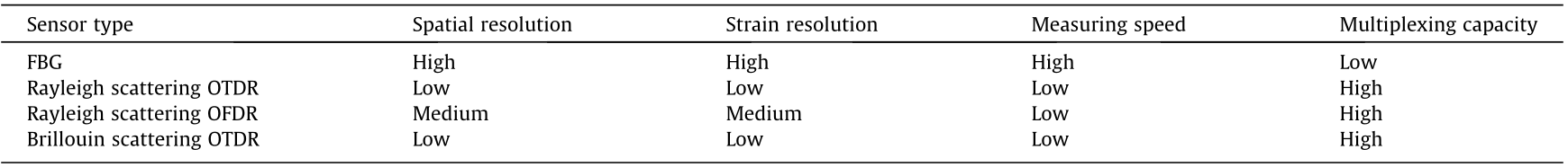
The main advantages of interferometric OFS technology are its high sensitivity and high resolution. The optical fiber Fabry–Perot interference sensor is the most widely used sensor in structural strain measurement. It is well suited for meeting special application requirements thanks to its strain resolution of better than 0.15 με, a measurement range that is larger than ±5000 με, a sensor length of less than 1 mm, and a temperature resistance of above 250 °C. Furthermore, it can be integrated into various structures for single-point strain measurement. Optical fiber sensors based on the Mach–Zehnder interference, Michelson interference, Sagnac interference, and so on can also be used to measure structural parameters such as strain, acceleration, and temperature. At present, two main drawbacks of interferometric optical fiber sensors limit their application: ① cross interference between multiple sensitive parameters; and ② difficulty in building a high-capacity sensor network with multiple measuring points through the use of multiplexing technologies.
The sensing technology based on optical fiber grating is a kind of quasi-distributed sensing technology. Its main advantages are its high spatial and strain resolutions, fast response speed, and the ability to realize absolute measurements and support the formation of a high-capacity sensor network with multiple measuring points through the use of multiplexing and other technologies. It can realize high-speed sampling and processing of sensor signals ranging from static-state signals to signals above megahertz using wavelength scanning laser demodulation, small-scale diffractiongrating charge-coupled device (CCD) solid-state spectrometer demodulation, micro-integrated arrayed waveguide grading (AWG) demodulation, and other technologies. In addition, it permits the miniaturization of airborne demodulators, which effectively reduces their size and weight.
At present, FBG sensing technology has been applied for the inflight measurement of various flight vehicle structures, including key structural parts such as wings, fuselage, tails, and landing gear, as well as the fuel tanks of space shuttles, solid rocket motors, satellite solar panels, and so on. These applications of this technology facilitate the real-time monitoring of several parameters such as strain, displacement, acceleration, and temperature. However, this technology has been tested over only a small number of flight tests; therefore, the amount of available measurement data is limited. A large number of flight verification tests are needed to effectively verify the reliability of the sensor deployment methods and the long-term performance of the sensor systems. Furthermore, there are still a few outstanding issues with respect to the highprecision monitoring of large-scale structural parameters and the reliability of these systems in engineering applications.
Distributed OFS technology has outstanding advantages when used for long-distance continuous sensing and monitoring. It uses optical fiber itself as a sensing unit and a signal transmission medium; hence, there is no need to design additional sensing elements. Measurement is based on the scattering principles. This technology allows continuous sensing of spatial distribution and changes in physical quantities such as strain and temperature along the optical fiber transmission path, which facilitates longdistance and wide-range (up to several kilometers) sensing and networking. At present, distributed OFS technology based on Rayleigh and Brillouin scattering and other principles is the dominant technology in structural monitoring. The strain measurement range can reach ±10 000 με, and the operating temperature range is from –268 to 900 °C. However, this technology has the drawback of having a low demodulation rate, which normally ranges from a few hertz to dozens of seconds and can take as long as a few minutes. Consequently, it is difficult to realize high speed and dynamic parameter measurements. Moreover, its measurement sensitivity, resolution, and demodulation rate decrease significantly with the increase of sensing distance, and it suffers from reliability problems similar to those of FBG sensing technology in engineering applications. Distributed acoustic sensing technology has high temporal and spatial accuracies, dynamic quantitative detection, and large-scale measurement. It has good application prospects in the vibration monitoring of aircraft structures, but its detection sensitivity is relatively low. These drawbacks limit the wider application of distributed OFS technology; therefore, they need to be resolved on a priority basis. In recent years, a significant amount of effort has been put into developing multi-level and multiparameter distributed sensing technologies to improve the detection sensitivity, temporal and spatial resolutions, demodulation rate, and robustness of the monitoring system.
《3.3. In-flight optical fiber real-time monitoring method》
3.3. In-flight optical fiber real-time monitoring method
Development of the OFS method for monitoring flight vehicle structural deformation involves the following technologies: optical fiber sensor deployment methods, sensor networking technology, signal acquisition and processing, dynamic real-time deformation reconstruction, and so on. Considering the long-term performance and reliability of the monitoring system, the optical fiber sensors, data acquisition equipment, and networking system used in a flight vehicle must meet the requirements of light weight, small size, high speed, large capacity, and high precision. Furthermore, optical fiber technologies have good compatibility and durability after being installed in a flight vehicle, which ensures their high reliability.
3.3.1. Sensor deployment
There are currently two main ways to deploy optical fiber sensors onto structures: surface mounting and implanting [18]. The former method fixes the optical fiber sensor onto the structure’s surface using adhesive, metal welding, or other means. This deployment method is widely used in the short-term testing stage and has a minor impact on the performance of the structure. However, there are a few problems in its long-term usage, such as falling off caused by gel aging or fiber breakage. Implanting is used to embed a sensing optical fiber inside the composite-material structure during the manufacturing process to form a sensing network. Subsequently, structures with sensing capability are assembled onto the flight vehicle to carry out in-flight monitoring. The advantage of this method is that the sensing optic fiber is protected by the composite-material structure, which prevents it from falling off or being damaged due to the influence of the external environment. However, the core diameter of the embedded optical fiber is usually larger than that of the reinforced fiber, which affects the mechanical properties of the structure. Moreover, the optical fiber gradually suffers fatigue cracks under the action of concentrated stress, affecting the service life of the sensor.
3.3.2. Signal demodulation
The main device that performs signal acquisition and processing functions in a monitoring network is the demodulator. The demodulation technologies commonly used by the FBG network signal demodulation unit include the tunable filtering method, tunable laser-scanning method, CCD spectrometer measurement method, AWG demodulation method, and edge-filtering method. The ideal airborne demodulation device should have high demodulation accuracy and speed, large sensor multiplexing capacity, and good stability. Several typical demodulation methods are compared in Table 2. Of these technologies, the first four exhibit good applicability for in-flight monitoring. Among these four technologies, the tunable filtering method and the tunable laser-scanning method have large measurement range, high demodulation accuracy, fast acquisition speed in the order of kilohertz, strong dynamic measurement ability, and large multiplexing grating capacity, which give them salient advantages in high-precision demodulation and high-frequency dynamic signal measurement.
《Table 2》
Table 2 Performance comparison of typical demodulation methods.

The CCD measurement method is highly stable, making it suitable for high-speed demodulation in a high-capacity multiplexing network for in-flight monitoring. However, it has poor measurement range and relatively low demodulation accuracy. Edge filtering, matched filtering, chirped grating, and other demodulation methods have poor measurement range, demodulation accuracy, and network multiplexing capacity, which limit their application for in-flight monitoring. AWG demodulation technology, which has developed rapidly in recent years, exhibits salient advantages in the high-speed demodulation of high-frequency dynamic signals above megahertz [21].
Signal demodulation performed by a distributed optical fiber monitoring network using the OTDR and OFDR technologies is mainly based on the principles of light intensity detection and coherent detection. The network signals are demodulated jointly by a photodetector, high-speed acquisition system, and other related algorithms. At present, the demodulation rate of distributed sensors is relatively low. Therefore, it is difficult to realize high-speed and high-accuracy multi-parameter demodulation of high-frequency dynamic signals in the presence of a large number of densely distributed network measurement points. In addition, it is necessary to reduce the volume and weight of the system while increasing its stability and reliability, which can improve the adaptability of the system to the in-flight monitoring environment.
3.3.3. Deformation reconstruction
The real-time reconstruction of dynamic deformation of the flight vehicle structure is mainly based on transient strain field data, which are obtained by the optical fiber monitoring network through high-speed demodulation and processing. The deformation field represented by physical quantities such as displacement is established using a deformation reconstruction algorithm. At present, commonly used deformation reconstruction algorithms include the reverse finite-element method, modal analysis method, and Ko displacement method [9,22]. The ideal aircraft structure deformation reconstruction algorithm should have high reconstruction accuracy, good real-time performance, and strong antiinterference ability. Typical deformation reconstruction algorithms are compared in Table 3. Among these algorithms, the reverse finite-element method is relatively more suitable for the realtime monitoring of dynamic deformation because it exhibits the highest accuracy and real-time performance, adapts to all kinds of boundary conditions, and can reconstruct a deformation without considering the structural mechanical parameters and external loads.
《Table 3》
Table 3 Performance comparison of deformation reconstruction methods.

《4. Reconstruction algorithm》
4. Reconstruction algorithm
《4.1. Inverse finite-element method》
4.1. Inverse finite-element method
The inverse finite-element method (iFEM) is a structural deformation reconstruction method that was proposed by Tessler et al. [23] in the early 21st century. Based on an idea similar to the finiteelement method, this method works as follows: ① Define the elements of the problem by theoretically analyzing the mechanical properties of the structure. ② Construct the elements using the mechanical model of the structure in conjunction with the element shape function. ③ Determine the element geometry, number of nodes and their degrees of freedom, and the strain–displacement matrix. ④ Discretize the structure to be solved using the constructed elements. ⑤ Gather the measured strain data from all the monitoring points and establish the error function between the measured and calculated strain fields using the least squares method. ⑥ Obtain the degrees of freedom of all the element nodes of the structure by solving the minimum value of the error function, thus completing the construction of the structural deformation field.
The input for structural deformation reconstruction using the iFEM is the strain measurement data obtained from the monitoring network. The deformation parameters are calculated using the system equation established by minimizing the error between the measured and calculated strains. The output consists of the deformation amplitudes of the element nodes of the structure. The key steps of the iFEM include strain data acquisition, element construction, and minimum error calculation.
The development history of the iFEM is as follows: In 2003, Tessler et al. [23] used the least-squares variational principle to analyze the plate and shell structures based on the first ordershear deformation theory. They reconstructed the deformation field based on the strain–displacement equation, which was obtained by using the least squares method to process the calculated and measured strains on the surface of the structure. The resulting reconstruction method was known as the iFEM method [23]. As the deformation field is reconstructed according to the strain–displacement correlation, the material properties, inertia, load, structural damping, and other parameters are not required. In 2010, Gherlone et al. [24] proposed the concept of the iFEM beam element based on the Timoshenko beam theory, realizing the real-time reconstruction of the static/dynamic deformation field of a 3D beam frame structure based on the strain measurement data. In 2013, Cerracchio et al. [10] extended the iFEM to cover composite laminate and sandwich structures by introducing the Refined Zigzag Theory into the iFEM, thereby paving the way for the real-time deformation reconstruction of the compositematerial structure of a flight vehicle. In 2018, Kefal et al. [25] and Tessler et al. [26] proposed the large-displacement, nonlinear, and dynamic deformation reconstruction method based on the iFEM and the step-by-step increment method. This method has important application value in the structural monitoring of various types of structures with large dynamic deformation, including fixed-wing aircraft wings, morphing aircraft skin, aerostat airbags, satellite solar sails, solar sail spacecrafts, and space telescope sun visors.
The National Aeronautics and Space Administration (NASA) regards the iFEM-based deformation reconstruction technology as being of great importance due to its obvious advantages in the real-time monitoring of a flight vehicle structure. The technology has gradually developed from laboratory to real-world application [27–31]. Its main advantages include: a high speed solution of the dynamic deformation field, good real-time performance, no requirement to consider the material properties and complex external loads, adaptability to structures with complex profiles, and the ability to reconstruct the deformation field with high precision using relatively sparse measuring points. From 2012 to 2016, a flight test project funded by the NASA Armstrong Flight Research Center (AFRC) through the Center Innovation Fund was carried out to verify the overall performance of the real-time structural deformation-monitoring technology. This verification was based on an optical fiber sensor network and the iFEM reconstruction technology. A comprehensive analysis of the accuracy, realtime performance, application cost, adaptability to the flight environment, and safety and reliability was carried out. This project paved the way for the application of this technology in the monitoring of various flight vehicle structures.
《4.2. Modal analysis method》
4.2. Modal analysis method
In 1995, Foss and Haugse [11] proposed a modal analysis method. It considers structural deformation as the summation of modal deformations of different orders—that is, the strain and displacement fields are expressed as the weighted linear combination of modal components of different orders. First, the vibration modes of the structure are analyzed using numerical, analytical, or experimental methods. The modal order is chosen, and the modal coordinates and strain modal shape matrix are obtained. Second, the strain measurement data are obtained by the monitoring network, and the strain field is calculated using the transformation equation between the strain matrix of the measuring points and the strain matrix of the whole field. Lastly, the displacement field is obtained using the strain–displacement equation, thus achieving the reconstruction of the deformation field. The NASA Langley Research Center (LRC) evaluated the applicability of the modal method in reconstructing the elastic deformation of plate and shell structures. As the reconstruction accuracy of this method depends on accurate structural modeling and modal analysis, the selection of the modal order, sensor layout, and properties of the structural material will significantly affect the reconstruction accuracy. This limits the applicability of this method in the real-time monitoring of flight vehicle structural deformation.
《4.3. Ko displacement method》
4.3. Ko displacement method
The Ko displacement method is a deformation reconstruction method proposed by Ko and Richards in 2007, based on the strain integral principle and the Euler–Bernoulli beam force model [9]. This method performs section-by-section processing of the beam structure and deploys strain measuring points accordingly. Subsequently, it establishes the differential equation of strains at the measuring points and the deformation displacement vectors based on the assumption of pure bending of the beam, as proposed by Euler and Bernoulli. Finally, it obtains the deformation displacement field through polynomial extrapolation and integral operation. The Ko displacement method has been gradually improved to a level at which it can reconstruct various types of deformations occurring in plate and shell structures including bending, torsion, and hybrid deformation. In 2009, the NASA AFRC used the Ko displacement method and an optical fiber sensor network to carry out a ground loading test on the double cone wings of the Ikhana unmanned aerial vehicle (UAV). In the test, a reconstruction of wing bending and torsion deformations was realized, and the reconstruction results were compared with those of the finiteelement analysis to verify the accuracy of the Ko algorithm. Later, the NASA AFRC carried out a ground loading test on the full-scale wings of the AeroVironment Global Observer UAV in 2010. The technical feasibility of reconstructing large-scale wing deformation using the Ko displacement method was verified in the test by comparing the performance of the resistance strain gauge and visual measurement methods.
《5. Application cases》
5. Application cases
The optical fiber sensors used for in-flight monitoring are usually networked utilizing two technologies [32–35]: the quasidistributed networking technology based on the multiplexing principle and fiber grating sensor, and the distributed networking technology based on the OFDR principle. A quasi-distributed monitoring network based on FBG multiplexing can obtain accurate measurements from the monitoring points; for example, it can measure the direction and magnitude of the main strain with grating strain sensors, accurately determine the coordinates of the deformation points, and acquire and process high-frequency dynamic signals at high speed using a small lightweight airborne demodulator. However, as the number of monitoring points depends on the number of FBGs, the whole network cannot be monitored continuously, and the areas without grating sensors are blind areas. Unlike the FBG muliplexing technology, the OFDR technology makes any section of the optical fiber a sensing unit, facilitating the continuous monitoring of any spot in the whole network. However, this type of sensor network has a few deficiencies with respect to multi-parameter high-accuracy measurements, accurate positioning, high-frequency dynamic measurements, demodulation rate, device miniaturization, and so on. In addition, the high-reliability deployment of optical fiber sensors is one of the most critical challenges in engineering applications. Currently, the main methods for deploying an OFS network on a structure include sticking, welding, and embedding. Many application cases have proven the feasibility of these methods. However, these sensors are easily damaged when subjected to great material stress when flying under severe conditions, such as storms, lightening, or high turbulence air. Hence, their robustness is an outstanding issue that needs further research.
《5.1. Aircraft》
5.1. Aircraft
In the mid-1990s, the NASA AFRC launched an OFS technology Research and Development (R&D) project to study optical fiber monitoring technology and systems based on the principles of FBG multiplexing, OTDR, and OFDR. In 1999, NASA carried out inflight tests on a prototype of an FBG multiplexing optical fiber monitoring system installed on the platform of an F/A-18 fighter [35,36]. However, these tests revealed that the performance of the light source (a tunable laser) of the prototype system did not meet the requirements for in-flight tests: The sampling rate of the monitoring system was as low as 0.01 Hz under the influence of vibration and temperature, and there was only a single acquisition channel. Consequently, the prototype system could not monitor parameters such as strain and temperature in real time, which meant that the flight test failed to achieve the expected verification goals.
Later, to meet the performance requirements of airborne equipment in a flight environment, the NASA AFRC launched a special R&D project to develop a highly robust and high-speed airborne fiber optic sensing system (FOSS) based on the OFDR and weakreflection FBG principles. In this project, wing deformationmonitoring technology verification flight tests were carried out on the Ikhana UAV in 2008, as shown in Fig. 1 [30]. In the tests, the total number of sensors in the optical fiber monitoring system was 16 000, the maximum sampling frequency of the demodulation device was 100 Hz, there were eight demodulation channels, the device size was 190.5 mm × 330.2 mm × 330.2 mm, and the weight was 13.61 kg. A total of 2880 FBG sensors, 16 groups of resistance strain gauges, and eight thermocouples were deployed on both wings for deformation measurement, error compensation, and comparative verification, as shown in Fig. 1(b) [30]. Using the test data of the high-resolution high-speed optical measurement system as the benchmark, the Ko displacement method was utilized to reconstruct the two-dimensional (2D) deformation of the wings, thus completing the ground calibration test of the optical fiber monitoring system. Subsequently, a total of 18 flight tests were carried out, amounting to a total of 36 flight hours. These flight tests verified the applicability of the optical fiber monitoring system under flight conditions. The flight test results showed that the optical fiber monitoring data were basically consistent with the monitoring data obtained using the resistance strain gauges, as shown in Fig. 1(d) [30].
《Fig. 1》

Fig. 1. OFS system verification flight test conducted by the NASA AFRC on the Ikhana UAV [30]. (a) Ikhana UAV with the optical fiber monitoring system installed. (b) The optical fiber sensor network and layout of the in-flight monitoring system.  is the distance between two adjacent sensing points. 1 in = 2.54 cm; 1 ft = 30.48 cm. (c) Ground calibration test. (d) Comparative verification of the flight measurement data.
After the successful flight test on the Ikhana UAV, the NASA AFRC installed the OFS system on the Global Observer UAV and carried out six flight tests in 2010, as shown in Fig. 2(a) [31]. The deployed sensors and the installed airborne demodulation equipment are shown in Fig. 2(b) [31]. In five flight tests, the OFS system successfully recorded the strain data of the wings and fuselage. In addition, NASA carried out ground loading tests using the Global Observer UAV as the experimental platform. Using visual measurement data as the benchmark, the applicability of FOSS and the Ko displacement method in the real-time deformation monitoring of large-size wings was verified on full-scale wings, as shown in Fig. 2(c) [31]. The test results showed that the displacement measurement error of the 2D bending deformation of the 175 ft (1 ft = 30.48 cm) full-scale wing structure was ±2.7 in (1 in = 2.54 cm). Increasing the number of FOSS strain measurement points beyond a certain number did not improve the deformation reconstruction accuracy any further. This behavior indicates that the deformation reconstruction accuracy does not increase in proportion to an increase in the number of monitoring points. The reason for this phenomenon is complicated and requires an in-depth analysis. In addition, the deformation reconstruction algorithm should be robust enough to adapt to incomplete flight measurement strain data—that is, the deformation reconstruction accuracy should meet the flight monitoring requirements even if the measurement data obtained from the optical fiber monitoring network are incomplete.
《Fig. 2》

Fig. 2. FOSS ground verification test on the Global Observer UAV [31]. (a) FOSS system verification flight test; (b) airborne demodulation device and deployed sensors; (c) ground test of wing deformation monitoring.
In 2014, the NASA AFRC developed a lightweight and miniaturized airborne FOSS monitoring system. Its demodulation device weighed 2.72 kg, measured 88.9 mm × 144.8 mm × 304.8 mm, had a maximum sampling frequency of 100 Hz, and consisted of four channels and 8000 sensors. In 2017, NASA carried out a deformation monitoring flight test on the X-56 morphing wing UAV, shown in Fig. 3(a) [31]. The optical fiber monitoring network, airborne demodulation device, and monitoring signals are shown in Fig. 3(b) [31]. The test data showed that the reconstructed 2D wing deformation obtained using the optical fiber monitoring data and Ko displacement method was consistent with the measurement results of the resistance strain gauge. The NASA AFRC achieved real-time deformation monitoring and wing deformation feedback control, which confirmed the applicability of the optical fiber monitoring system for in-flight deformation monitoring.
《Fig. 3》
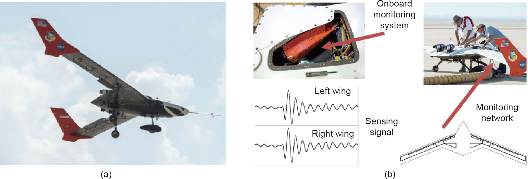
Fig. 3. OFS system verification flight test on an X-56 morphing wing UAV [31]. (a) The X-56 morphing wing UAV used in the NASA flight test; (b) optical fiber network, airborne demodulator, and monitoring signal.
In 2015, Kressel from the IAI Engineering Department of Bengurian Airport in Tel Aviv, Botsev from Tel Aviv University, and Gupata from the National Aerospace Laboratories of India deployed an FBG multiplex sensor network on an Indian Dawn UAV for an in-flight with-load monitoring test. The test was used to evaluate the applicability of optical fiber monitoring technology for aircraft SHM, as shown in Fig. 4 [33]. Its main objective was to gauge the accuracy level of the optical fiber monitoring system for measuring strain and calculating flight parameters, and to verify the applicability of principal component analysis (PCA) and an artificial neural network (ANN) for flight load calculation, vibration analysis, and damage identification. The tail truss was selected as the monitoring object in the test. During the fabrication of the composite-material tail truss, four polyimide-clad optical fibers with four FBGs on each fiber were implanted into the structure according to the layout shown in Fig. 4(b) [33]. The fibers were used to measure the strain of the tail truss structure caused by deformations in the horizontal and vertical directions during takeoff, cruising, and landing. The WX-04M demodulator, manufactured by Smart Fibres, had a sampling rate of 2.5 kHz. It was used as the airborne demodulation and processing device, and as a data recorder for collecting and storing optical fiber monitoring signals in real time. The ANN model was trained in the off-line mode using the finite-element simulation data, and the structure load was estimated using the trained ANN model and strainmonitoring data. The PCA algorithm was used to analyze and identify damage signals and evaluate structural integrity. This study verified the applicability of OFS technology and an ANN algorithm for aircraft structure monitoring. However, it did not realize realtime data processing.
《Fig. 4》
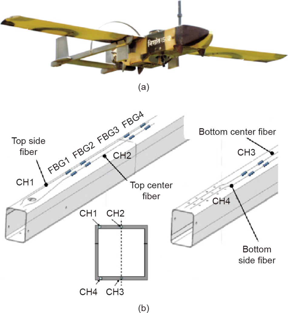
Fig. 4. Flight test of FBG multiplex sensor monitoring technology on a Nishant UAV. (a) A Nishant UAV; (b) layout of four optical fibers and FBGs implanted in the tail truss structure. CH: channel. Reproduced from Ref. [33] with permission of IOP Publishing, Ltd., © 2015.
Wada of the Japan Aerospace Exploration Agency (JAXA) and Murayama of Tokyo University cooperated to carry out a flight verification test of the distributed OFS monitoring technology using the OFDR-FBG on a medium-sized jetliner in 2018 [34]. The purpose of this test was to study the implementation of intensive and high-speed monitoring on large-sized aircraft structures. The optical fiber monitoring system used in the test utilized the weak-reflection FBG with a length of several meters as the sensing element. The spatial distribution information of the FBG reflection spectrum was calculated in the frequency domain using the OFDR technology, thus realizing the demodulation of parameters such as structural strain and temperature. The highest spatial resolution speed reached the sub-millimeter level, the demodulation rate was 151 Hz, and the repeated error was ±8.2 picometers (pm), corresponding to ±6.8 με. The layout of the airborne sensor and the demodulation device is shown in Fig. 5(a) [34]. The two lines of FBGs were fixed by an adhesive onto the longitudinal beam structure with an FBG length of 4.5 m, as shown in Fig. 5(b) [34], and onto the bulkhead with an FBG length of 350 mm, as shown in Fig. 5(c) [34]. The demodulation device was installed inside an airborne box with dimensions of 425 mm × 450 mm × 220 mm. To verify the accuracy of the optical fiber monitoring data, the researchers deployed a series of resistance strain gauges and thermocouples at the positions of the FBGs on the bulkhead and longitudinal beam, and used the NR600 data recorder (Keyence Co., Ltd., Japan) to collect the strain and temperature data of the electrical sensors. A notebook computer was used to store real-time optical fiber monitoring data and electrical sensor measurement data. In the flight test, the aircraft took off from Nagoya Airport in Japan and flew over the southern part of the Pacific Ocean before returning. The flight height and time were 15 000 ft and 80 min, respectively. The main actions included takeoff, taxiing, turning, and landing. During the test, acceleration and gyroscope data were acquired by a Global Positioning System (GPS)-aided inertial navigation system. The structural responses of the bulkhead and longitudinal beam during different flight actions were analyzed using the acceleration and gyroscope data in conjunction with historical strain-monitoring data. The flight test data showed that the historical strain data measured by the optical fiber were consistent with the structural stress analysis data acquired by the electrical sensors during different flight actions, as shown in Fig. 5(d) [34]. Although the deformation field in the stress concentration area was not reconstructed accurately, the importance of deformation measurement in structural fatigue analysis was highlighted. In 2019, Wada et al. [4] conducted a similar flight test to verify the technical feasibility of applying distributed optical fiber sensor technology based on the OFDR-FBG for the wing strain monitoring of a medium-sized jetliner.
《Fig. 5》
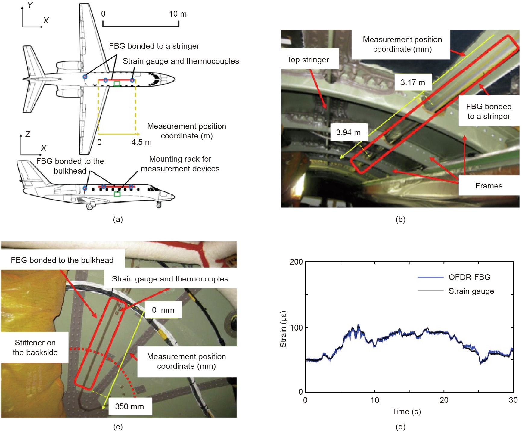
Fig. 5. Verification flight test of distributed optical fiber sensor monitoring technology based on OFDR-FBG carried out jointly by the Japan Space Agency and Tokyo University. (a) Deployment scheme of the airborne sensors and demodulation device; (b) photo of sensors deployed on the longitudinal beam of the aircraft; (c) photo of sensors deployed on the aircraft bulkheads; (d) comparison of flight test data between OFDR-FBG and the resistance strain gauge. Reproduced from Ref. [34] with permission of IOP Publishing, Ltd., © 2018.
In 2019, Kwon from the Korea Advanced Institute of Science and Technology (KAIST) and Kim from the Korea Aerospace Research Institute (KARI) cooperated to carry out a flight verification test of the quasi-distributed optical fiber sensor monitoring technology. The technology was based on FBG multiplexing and a CTLSELA single-wing two-seat small aircraft was used as the platform [20]. The key parts of the aircraft, such as the wings, horizontal stabilizer, vertical tail, landing gear, and propeller, were all made of carbon fiber composite materials. The aircraft had a no-load weight of 326 kg, a maximum takeoff weight of 600 kg, and a cruise speed of 240 km·h–1 . During the test, the wing was chosen as the monitoring object. The overall layout of the airborne optical fiber monitoring system is shown in Fig. 6(a) [20]. When the wing was manufactured, an acrylate-clad optical fiber with six FBGs was embedded and solidified between the lower wing beam cap and the wing beam rib for strain monitoring. The layout of the optical fiber monitoring points and the process of implanting the wing are shown in Fig. 6(b) [20]. An FBG temperature sensor was fixed with adhesive on the inner surface of the lower skin of the wing for monitoring the temperature change. The measured temperature change was used to compensate the corresponding strain measurement error. A Bitelinx BIG-SM04 demodulator (Bitelinx Inc., Republic of Korea) was used to collect the data from the optical fiber monitoring network, and the aircraft attitude and other flight parameters were acquired by the altitude and heading reference system. A purpose-built data acquisition, processing, and storage (DAPS) module was used to convert the demodulated spectrum data into strain data. The converted data were then stored in the flash memory along with the flight parameter data. The measured flight time strain historical data are shown in Fig. 6(c) [20]. The strain–load equation was established based on a ground calibration test and was used in conjunction with the flight verification data to verify the ground calibration data and obtain the correlation coefficient. During the flight test, the main actions of the aircraft included takeoff, climbing, descending, and an inclined turn. An analysis of the force conditions and flight parameter data of the wing under different flight conditions showed that the average error of the load factor—that is, the thrust-to-weight ratio of the wing—calculated using the optical fiber monitoring data was 4.19%. This small error verified the feasibility of applying FBG multiplex sensing technology for the wing load monitoring of the aircraft.
《Fig. 6》

Fig. 6. An FBG multiplexing monitoring technology verification flight test jointly conducted by KAIST and KARI. (a) Overall layout of the airborne optical fiber monitoring system. DAPS: data acquisition, processing, and storage. (b) Positions of the optical fiber monitoring points and the method of sensor implantation in the wing. (c) Historical strain data measured during the in-flight test. Reproduced from Ref. [20] with permission of SAGE Publications, © 2019.
《5.2. Spacecraft》
5.2. Spacecraft
A spacecraft flying in the atmosphere or in space experiences various types of structural deformations with different amplitudes due to high temperature, radiation, vacuum, microgravity, vibration, impact, and other complex and harsh environmental factors, which degrade its performance. Since the 1990s, the European Space Agency (ESA), NASA, the US Naval Research Laboratory (NRL), and other institutions have carried out research on optical fiber monitoring technology and spacecraft structure monitoring systems [35–43]. The research has promoted the application of this technology in manufacturing, testing, and life-cycle health monitoring of spacecraft structures [44–47].
In 2005, the ESA disclosed its research plans pertaining to the development of optical fiber monitoring technology for measuring spacecraft parameters. These plans included [38]: ① deploying optical fiber sensors on satellite structures that required high dimensional stability, where the deployed sensors could monitor structural deformation caused by thermal radiation and vibration in real time; ② embedding optical fiber sensors in adaptive composite-material structures with a self-driving active morphing function for the real-time monitoring of active deformation, which can compensate for passive deformation or suppress vibration; ③ attaching or embedding optical fiber sensors on the surface of or inside the large low-temperature storage tank and compositematerial inner tank of a reusable launch vehicle, such as a space shuttle, for the real-time monitoring of static and dynamic strain; ④ using optical fiber sensors and a high-speed demodulation device with a demodulation frequency on the order of kilohertz to measure acoustic and vibration interference signals from a reflector antenna in a ground test; and ⑤ deploying optical fiber sensors on the solar sail structure to monitor the dynamic strain and deformation. In 2009, the ESA carried out a flight test on the Fiber Sensor Demonstrator (FSD) onboard the Proba-2 satellite, which demonstrated the adaptability of the FSD to the space environment [39].
From 2009 to 2010, the NASA AFRC and LRC jointly carried out a FOSS ground monitoring test on the full-scale composite-material passenger cabin of a manned spacecraft, as shown in Fig. 7 [30,31]. In the experiment, optical fiber sensors were deployed on the windows of the passenger cabin and the interface section, and a fourchannel demodulator was used to acquire the optical fiber monitoring signals. The accuracy of the structural strain optical fiber monitoring data was verified through a cabin pressurization test and the corresponding finite-element modeling and calculation. In the structural destruction test carried out at the end of the experiment, the FOSS was always able to continuously and reliably monitor the strain, and successfully captured the shock wave signal at the moment when the passenger cabin structure broke down.
《Fig. 7》
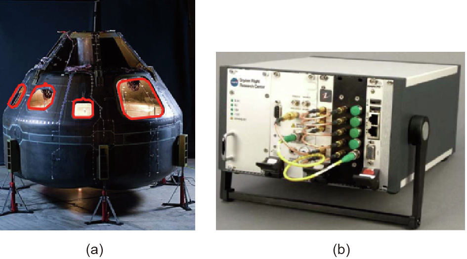
Fig. 7. A ground verification test on the FOSS monitoring of a full-scale compositematerial cabin carried out jointly by the NASA AFRC and LRC [30,31]. (a) Passenger cabin of a manned spacecraft. (b) FOSS system developed by NASA.
The NASA AFRC and the Commonwealth Scientific and Industrial Research Organization (CSIRO) jointly carried out an optical fiber monitoring test from 2011 to 2015 on a spacecraft thermal protection system. In the test, the FOSS was used to monitor the strain, temperature, deformation, impact damage, and other important parameters of the thermal protection structure, as shown in Fig. 8 [30,31]. The test verified the applicability of the FOSS in the health monitoring of the spacecraft thermal protection structure.
《Fig. 8》

Fig. 8. Experimental verification of the FOSS monitoring of the spacecraft thermal protection structure, jointly carried out by NASA and CSIROO [30,31].
Starting in 2013, the Instituto Nacional de Técnica Aeroespacial of Spain carried out a two-year flight test of an optical fiber monitoring system onboard the OPTOS nano-satellite. Two FBGs were used to monitor the structural strain and temperature of the satellite in orbit. The monitoring signal was processed by a highly integrated micro lightweight demodulation device, and the obtained data were compared with the ground calibration data to verify the applicability of the optical fiber monitoring system in the space environment [41].
The Shandong Institute of Aerospace Electronics Technology carried out a flight test of the FBG sensor system onboard a satellite in 2016, realizing the in-orbit monitoring of temperature and strain inside and outside the satellite cabin [48]. The optical fiber sensor monitoring system developed by the Beijing Information Science & Technology University (BISTU) underwent a flight test in 2018 onboard the satellite Xiangjiang Xinqu, owned by the Tianyi Research Institute. In the test system, a strain-monitoring network consisting of a single strain measurement point and ten temperature measurement points was constructed through FBG multiplexing. The signals acquired by the measurement points were demodulated by a tunable laser-scanning method, thus realizing strain and temperature monitoring of the structure of the satellite in orbit. Fig. 9 shows the onboard optical fiber monitoring system. After more than two years of flight tests, the adaptability of the optical fiber sensors and the micro lightweight demodulator in the space environment was verified. Since then, BISTU has cooperated with China Academy of Space Technology and other institutions to carry out a series of flight verification tests for optical fiber sensing systems on various types of satellites, and is carrying out a space station monitoring test based on optical fiber sensing systems, as shown in Fig. 10.
《Fig. 9》
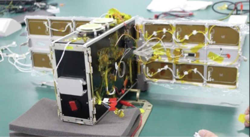
Fig. 9. Verification flight test for an optical fiber sensor monitoring system onboard the Xiangjiang Xinqu satellite.
《Fig. 10》

Fig. 10. A series of flight verification tests for optical fiber sensing systems on various types of satellites carried out by BISTU.
《5.3. Rockets and missiles》
5.3. Rockets and missiles
In 2015, NASA’s Launch Services Program funded an R&D project on the development of optical fiber monitoring system for launch vehicles as shwon in Fig. 11 [30,31]. The NASA AFRC and Marshall Space Flight Center (MSFC) cooperated in the R&D of airborne optical fiber monitoring equipment for the real-time measurement of multiple physical quantities during the life cycle of the launch vehicles. The aim of the project was to replace traditional flight-testing devices such as resistance strain gauges, accelerometers, thermocouples, gyroscopes, and propellant sensors with the optical fiber monitoring equipment. The monitored parameters included strain, 2D/3D deformation, vibration, temperature, liquid level, and electromagnetic field. The main tasks in the project included: ① improving the technical indicators of FOSS, which included increasing the demodulation frequency to 40 kHz so that the vibration signal and acceleration could be measured, and increasing the monitored parameters to include fuel level and electromagnetic and high-frequency fields; ② developing an airborne demodulation device according to the rocket structure and flight environment; and ③ cooperating with the NASA Engineering & Safety Center and commercial aerospace companies to carry out flight tests. The R&D work improved the performance of the FOSS and promoted the application of OFS in the deformation monitoring of spacecraft structures during the whole life cycle of spacecrafts [45–47].
《Fig. 11》

Fig. 11. Optical fiber monitoring system for launch vehicles jointly developed by the AFRC and Marshall Space Flight Center (MSFC) in a project funded by NASA’s Launch Services Program [30,31].
《6. Key issues》
6. Key issues
《6.1. Deployment of optical fiber sensors》
6.1. Deployment of optical fiber sensors
In the engineering application of flight vehicle structure monitoring technology, the first key issue to resolve is the reliable deployment of optical fiber sensors. Major considerations in sensor deployment include durability, measurement accuracy, and impact on the performance of the structure. At present, the main methods for deploying optical fiber sensors on a structure include sticking, welding, and embedding. All these methods have a few drawbacks when used in practical applications.
The sticking deployment method uses an adhesive to attach the optical fiber sensor (after sealing) directly or indirectly onto the structure surface. This deployment method has a minor impact on the properties of the structure and barely increases the weight of the airborne sensor. However, the optical fiber sensor deployed with this method is prone to breaking or falling off in complex and harsh flight environments, which means that its service life, safety, and reliability cannot be guaranteed. In order to ensure that the quality of sensor deployment meets the engineering requirements of flight vehicle structure monitoring, it is necessary to systematically study properties such as the interface strain transfer, mechanical strength, and durability of fiber–colloid–matrix materials with a multilayer structure.
The welding deployment method consists of welding the optical fiber sensor with a metal coating onto the structure using laser welding, ultrasonic welding, or other welding methods. The optical fiber sensors deployed by this method usually have high straintransfer efficiency, reliability, and durability under harsh flight conditions. However, the method adds a metal layer with a certain thickness to the exterior of the optical fiber. The welding not only increases the weight of the airborne system, but also causes stress concentration and high residual stress in the welding area, which affects the fatigue life of the flight vehicle structure.
The embedding deployment method consists of embedding optical fiber sensors into the interlayer of the structure during the composite-material structure manufacturing process to form a functional structure for deformation monitoring. The optical fiber sensors deployed by this method are protected by the structure matrix and hence will not undergo accelerated aging caused by exposure to harsh flight conditions. The sensor deployment will increase neither the weight nor the aerodynamic structural shape. However, the mechanical properties and fatigue life of the composite-material structure are affected after the embedding of the optical fiber, and the stress concentration at the optical fiber–matrix interface will affect the sensitivity and service life of the optical fiber sensor.
In order to improve the reliability and measurement accuracy of the optical fiber sensor after its deployment in a flight vehicle structure, future research should focus on the following issues:
6.1.1. Fiber coating
At present, the commonly used materials for coating optical fibers include acrylate, polyimide, and other plastic materials. This type of coating layer cannot sufficiently protect the optical fiber in harsh environments, and can only withstand temperatures below 400 °C. The mechanical stability of the optical fiber can be improved by coating a metal layer onto its surface, which endows it with better durability for long-term use in harsh environments and allows it to withstand higher temperatures. At present, a variety of coating processes exist for forming a severalhundred-micron-thick metal coating of gold, aluminum, nickel, copper, or other metals onto the surface of an optical fiber. However, the interface mechanical strength and strain-transfer efficiency of different metal coating materials after the coating material has been bonded with the optical fiber and the structure matrix should be analyzed. Furthermore, the impact of metal coating thickness on the interface strength and strain transfer should be analyzed. By conducting extensive modeling and testing, as well as selecting a metal coating material and structural parameters that suit the application environment, it is possible to ensure high mechanical stability, high bonding strength, and minimum strain-transfer loss for the metal-coated optical fiber sensor after deployment.
6.1.2. Adhesive
For the sticking deployment method, the performance of the chemical adhesive is the key factor affecting the deployment quality of the optical fiber sensor. At present, epoxy adhesive is widely used to attach the optical fiber sensor onto the surface of the flight vehicle structure. This adhesive works well in ground tests or short-term flight measurement. However, it is not suitable for long-term monitoring of a flight vehicle structure. Although it adheres well with the structure matrix and optical fiber, the heterogeneous interface between the adhesive layer and the optical fiber coating will reduce the strain-transfer efficiency of the matrix to less than 90% after curing, thus increasing the structural deformation measurement error. In addition, the aging resistance of existing epoxy adhesives in a complex and harsh environment is not ideal, especially under high temperatures. Therefore, it is necessary to develop special adhesives and bonding processes that are suitable for flight vehicle monitoring applications, paying special attention to chemical adhesion, post-curing mechanical properties, and aging resistance.
6.1.3. Stress concentration
The sensing unit formed after the deployment of optical fiber sensors using the sticking, welding, or embedding deployment method is a multi-interface system composed of optical fibers, an intermediate, and a matrix. Under the action of a complex load, the heterogeneous interface of the sensing unit is likely to produce stress concentration. Long-term stress concentration will form microcracks in the optical fiber and the matrix. The growth of microcracks will cause fracture and failure of the sensor and will degrade the mechanical properties and shorten the fatigue life of the structure. Therefore, to minimize the stress concentration introduced by the deployment of optical fiber sensors, it is necessary to systematically study the core diameter, cladding/coating material, intermediate material, matrix compatibility, and deployment process parameters of the optical fiber.
6.1.4. Strain-transfer loss
The structural deformation reconstruction accuracy depends on the accuracy of measuring the micro strain of the structure matrix. When the strain field of structural deformation propagates to the heterogeneous matrix–optical fiber interface, micro elastic deformation will occur at the interlayer interface due to the strain field. The reaction to the matrix will produce a strain field that propagates in the opposite direction. Consequently, the matrix strain in the sensor deployment area is smaller than that in the other areas. The influence of this kind of micro-action mechanism on the matrix strain-transfer efficiency is usually ignored in the existing research on optical fiber deployment methods and technologies. However, experiments have shown that the matrix strain measurement error will increase significantly if these micro-action mechanisms are ignored, especially for matrix materials with a small Young’s modulus, such as composite materials, flexible materials, and hyper-elastic materials. Therefore, it is necessary to establish a strain-transfer loss model of the matrix–intermediate–optical fiber multi-interface system based on the principles of interface mechanics. In addition, the multi-interface system parameters should be optimized through the combined use of simulations to minimize the strain-transfer loss and realize high-precision matrix strain measurement.
《6.2. Layout of the monitoring network》
6.2. Layout of the monitoring network
A high-capacity optical fiber monitoring network with dense measuring points can be established using fiber grating multiplexing or distributed sensing technologies. The network can achieve a high spatial resolution for structural strain measurement without significantly increasing the volume and weight of the monitoring system [46–51]. However, densely distributing the monitoring points will increase the number of deployed optical fiber sensors and the amount of sensor transmission data to a certain extent, deteriorate the real-time signal demodulation and data processing performance, affect the reliability and durability of the monitoring network, and increase the operation and maintenance costs of the system. The ground test data obtained by the NASA AFRC from the optical fiber monitoring of 2D bending deformation of a full-scale wing on a Global Observer UAV indicated that the dense deployment of strain-monitoring points did not significantly improve the deformation measurement accuracy. For example, when the Ko displacement method was used to reconstruct the deformation and the number of strain-monitoring points was reduced by 13.55% and 51.61%, the resulting variations of tip displacement measurement errors were 0.09 and 0.11 in, respectively, which were very small. In 2017, Kefal and Yildiz [52] of the Research and Development Center of Composite Technology of Kordsa Global-Sabanci University (Turkey) also proposed deploying the strain-monitoring points sparsely on the wing sandwich structure and using the reverse finite-element reconstruction algorithm to measure the deformation of the structure with high accuracy. Therefore, it is necessary to intelligently design the monitoring network layout. The key is to strike a balance between the number of monitoring points and the accuracy of the deformation measurement. In this way, it is possible to use the smallest possible number of monitoring points to measure deformation in engineering applications.
《6.3. Airborne demodulator》
6.3. Airborne demodulator
An airborne demodulator is a key issue in the R&D of optical fiber monitoring technology and systems. In terms of functionality, the common characteristics of an airborne demodulation device include compactness, a light weight, low power consumption, and high reliability. It should also be able to adapt to different sampling rates and sensor capacities, and to show compatibility with the airborne avionics equipment used for data communication. It must also have environmental adaptability—that is, it should be able to adapt to different flight conditions such as vibration, high/low temperatures, and space radiation. The existing airborne demodulation devices developed by NASA, Smart Fibers, Bitelinx, and others have passed the ground and flight tests, thus preliminarily verifying their functionality and the environmental adaptability of the system. However, the existing system should be fully verified and evaluated in terms of performance indicators, adaptability to different airborne environments, long-term monitoring reliability, and so forth. It is necessary to improve the sensor capacity, high-frequency signal sampling rate, and stability of the airborne demodulation device under vibration and temperaturevarying conditions in order to meet the application requirements of different types of flight vehicles and complex flight environments. Furthermore, the volume, weight, and power consumption of the system should meet the in-flight operation requirements. Therefore, environmental adaptability tests, reliability tests, and flight tests must be carried out according to the relevant standards of airborne equipment, which can improve the performance and reliability of the system and make it suitable to carry out longterm monitoring.
《6.4. Deformation reconstruction algorithm》
6.4. Deformation reconstruction algorithm
The existing research on reconstructing structural deformation using the Ko displacement method, iFEM method, and modal analysis method in conjunction with strain measurement data usually uses ground tests to verify the algorithm accuracy through simulated loading and test comparisons, and to evaluate the applicability of different reconstruction algorithms for in-light deformation monitoring. However, there have been a few reports on flight tests of real-time deformation reconstruction technology for flight vehicle structures [53–57]. For real-time monitoring of the structural deformation parameters during flight, it is necessary to study the accuracy and efficiency of the reconstruction algorithm, and to streamline the algorithm structure in order to improve its execution efficiency under the condition that the reconstruction accuracy meets the measurement requirements. In addition, it is necessary to develop high-speed data acquisition and processing devices suitable for the flight environment, and to test the level of tradeoff between the deformation reconstruction accuracy and data processing efficiency in the highly dynamic ground simulation and flight test environments. On this basis, the software and hardware modules of the deformation reconstruction system should be optimized using the test data to make them suitable for the real-time monitoring of flight vehicle structural deformation.
《6.5. Ground calibration and flight measurement》
6.5. Ground calibration and flight measurement
To monitor the structural deformation of an aircraft using an optical fiber sensor network, a load calibration test should be performed on the ground to establish the quantitative relationship between structural deformation and the sensor measurement value. The actual flight deformation can be obtained by applying this relationship to the flight measurement data. Although this method of using ground calibration data to calculate flight parameters has been widely used, it has potential uncertainties. This is mainly because the structural loads of the aircraft during actual flight are more complex and diverse than the loads under the ground environment, such as the ambient temperature, air pressure, vibration, acceleration, and other parameters. This will introduce error into the actual flight measurement results. In order to obtain more accurate flight measurement results, systematic analysis and verification are needed for the ground simulation loading method, calibration data processing, test error correction, actual measurement data processing and statistical analysis, and so forth. These analyses and verifications can improve the compliance of the ground calibration data with the actual flight conditions and are, therefore, the key to accurately monitoring the structural parameters of the aircraft.
《6.6. Integration with an airborne system》
6.6. Integration with an airborne system
The objective of flight vehicle structural deformation monitoring is to integrate a small, lightweight, low-power-consuming, high-precision, high-efficiency, and high-reliability monitoring system into an airborne system in order to continuously monitor the structural deformation in real time during the whole life cycle [58–62]. The monitoring system provides valuable real-time data to support flight control by acquiring parameter information relating to strain, displacement, and vibration in time. This in turn helps to improve flight safety and reduce maintenance costs. To achieve this objective, it is necessary to integrate the airborne optical fiber monitoring system according to the specific avionics equipment interfaces of each flight vehicle. An optical fiber monitoring system consists of hardware and software systems. The former mainly consists of optical fiber sensors, a demodulation device, and a high-speed data acquisition and processing device. The latter is composed of a signal processing module, reconstruction algorithm module, and storage and display module. On this basis, the performance of the airborne system should be tested to ensure that the system meets the requirements for deformation monitoring over the whole life cycle of the flight vehicle.
《7. Future development》
7. Future development
Since the 1950s, flight vehicle structure monitoring equipment has undergone significant development, starting from mechanical sensors (mainly mechanical accelerometers and strain gauges) to electronic multi-parameter monitoring devices. This development is evolving in the direction of light transmission monitoring. Flight vehicle structure monitoring based on optical fiber sensor network has attracted the attention of many researchers because it is a promising application technology. Many studies on this technology have yielded practical and valuable research results. In the future, this technology is expected to be widely used in the monitoring of flight vehicle structural parameters. However, it should be noted that, although OFS technology is assumed to be one of the most valuable technologies among various types of aircraft structure monitoring technologies, it is not the only type of technology.
In order to promote the application of OFS technology in flight vehicle structure monitoring, it is necessary to solve various problems. These problems involve key theories, methods, core components, and devices needed for the sensor deployment and networking, demodulation, deformation reconstruction, and system integration of the airborne system. It is also essential to carry out engineering development in the areas of cost, performance, product, process, standards, and so on, so that high-efficiency and cost-effective airborne optical fiber monitoring products can be developed.
《7.1. Evolution paradigm》
7.1. Evolution paradigm
The development of optical fiber-based SHM (OF-SHM) is transitioning from the laboratory research stage to the engineering application stage. There are three types of basic evolution paradigms: the target paradigm, technology paradigm, and model paradigm. These three paradigms iterate constantly and fuse with one another during the development process, reflecting the dynamics of the evolution of OFS monitoring technology for flight vehicle structures.
7.1.1. Target paradigm
The target evolution paradigm mainly includes reducing the maintenance cost, innovating the design concept, and reducing the structure weight. The application goal of the first generation of OF-SHM is to reduce the maintenance cost. This is achieved by using optical fiber sensor data to monitor the health of the flight vehicle structure, reduce the detection time and cost, reduce the maintenance cost of the structure, and evaluate its remaining service life so that this can be extended and the use efficiency can be improved. The application goal of the second and third generations of OF-SHM is to innovate the design concept and reduce the structure weight. This is achieved by using the optical fiber monitoring data of the whole life cycle of the flight vehicle structure to carry out design innovation and optimization, put forward new material and structure design concepts that meet the in-flight monitoring requirements, and attain high performance and reliability while reducing the weight of the flight vehicle structure, thus maximizing efficiency and economic benefits.
7.1.2. Technology paradigm
The technology evolution paradigm mainly includes regular shutdown detection, non-real-time monitoring, and real-time monitoring of the whole life cycle.
In regular shutdown detection, the optical fiber sensors are deployed permanently onto the flight vehicle structure. However, it is not necessary to install airborne signal acquisition and processing devices. When the flight vehicle is parked, maintenance technicians connect the special detection device to the sensors to detect the structural state.
In non-real-time monitoring, an optical fiber sensor network is deployed on the flight vehicle structure, and the airborne signal demodulation device as well as the DAPS devices are installed onboard the flight vehicle. The measurement data are stored in the airborne recording device and are fetched regularly when the flight vehicle is parked.
In life-cycle real-time monitoring, an airborne optical fiber monitoring system is deployed on the flight vehicle structure for continuous monitoring of the structural state parameters during the life cycle of the flight vehicle. The monitoring system can process the data in real time during flight and transmit important information to the remote base station when needed, while maintaining safety.
7.1.3. Model paradigm
The model evolution paradigm mainly includes old aircrafts and UAVs (satellites, space detectors, etc.), and new military and civil flight vehicles. The key factor determining the evolution of the model paradigm is the efficiency–cost ratio, which mainly involves the improvement of performance, safety, and cost benefit. At present, the main driving force behind the application of optical fiber monitoring technology is to reduce the inspection and maintenance costs of old aircraft and improve the performance of UAVs at an acceptable efficiency–cost ratio. In the future, optical fiber monitoring technology will be gradually applied to new military and civil flight vehicles in order to attain higher performance, a higher safety level, and greater economic benefits.
《7.2. Standardization》
7.2. Standardization
It is necessary to conduct standardized development and certification of airborne optical fiber monitoring systems in order to meet the requirements of flight vehicle structure monitoring. The R&D of an airborne optical fiber monitoring system should be based on a set of scientific technical specifications and in-flight monitoring conditions that are suitable for the life-cycle monitoring of flight vehicle structures. The unit responsible for designing the monitoring systems should gather together the flight vehicle design, manufacturing, and test units to solve the key technical and device problems relating to each performance indicator of the airborne optical fiber monitoring system. It is also necessary to carry out technical verification of all aspects of R&D, including the design, manufacturing, system, airworthiness, and iteration of the design, in order to ensure that the system meets the requirements of in-flight monitoring before developing the design into products and establishing technical standards, product manufacturing, and test processes. The monitoring system should be utilized in military flight vehicles (especially new UAVs, aircraft over 14 years old, etc.), satellites, space detectors, and other aerospace vehicles.
《7.3. New materials》
7.3. New materials
Thanks to the development of material technology, the latest flight vehicle models use a large quantity of composite materials to reduce structural weight, improve flight performance, and reduce flight cost, thereby promoting the development of flight vehicle design and manufacturing technologies [62–65]. At the same time, a few novel-concept flight vehicles such as morphing aircraft need flexible skin, which boosts the development of new materials such as flexible composite materials [66–69]. While the emergence of new concepts in flight vehicle design and the application of new materials bring opportunities for the development and application of OFS and monitoring technologies, they also pose new challenges. Therefore, it is necessary to conduct well-targeted research on OFS and monitoring technologies in order to develop systems that are suitable for monitoring structures made of new materials. Research should be carried out in the following areas: sensor deployment, strain-transfer efficiency, sensor sensitivity, network layout, load calculation and reconstruction, system reliability based on deep knowledge of the composition, and the organization form and performance characteristics of each composite material.
《7.4. Intelligentization》
7.4. Intelligentization
Since the research field of artificial intelligence (AI) was formally established at the Dartmouth conference in 1956, it has passed through more than 60 years of evolution, despite several setbacks. In recent years, thanks to new technologies such as big data and cloud computing, as well as new methods such as deep learning, AI has entered a new era of development. AI has been increasingly used in aerospace and other fields, exhibiting the trends of interdisciplinary fusion, human–machine collaboration, autonomous control, and so forth [66–70].
In the field of optical fiber monitoring of flight vehicle structures, an important development direction is the use of intelligent algorithms for various tasks such as signal processing, multi-sensor data fusion, statistical pattern recognition, and life-expectancy assessment, as well as the utilization of high-speed, low-power dedicated microchips to develop intelligent airborne fiber monitoring systems. At the same time, optical fiber monitoring data can be fed back to the flight control system. The flight control parameters can be processed and adjusted in real time through intelligent control algorithms, which can enable the aircraft to maintain good flight stability and safety under different deformation states. In the process of intelligentization, the main problems that need to be solved include: ① how to make use of limited measurement data obtained in flight tests for train and refining the model algorithms, while considering the complex and changing flight environment and limited flight tasks; ② how to use efficient algorithms and high-performance chips to improve the accuracy of data processing and to enable real-time matching; and ③ how to develop an efficient and cost-effective intelligent monitoring system that can improve performance, ensure safety, and economize costs.
《7.5. Ecologization》
7.5. Ecologization
Ecologization is a new concept in single flight vehicle monitoring technology and an important direction for future development. This term refers to the combination of edge computing devices incorporating intelligent algorithms, such as light convolution neural networks, and optical fiber sensor networks in single flight vehicle monitoring. This combination results in a real-time airborne monitoring system with a range of capabilities including sensing, calculation, analysis, identification, evaluation, prediction, and decision-making.
With the evolution of single flight vehicle monitoring technology in the direction of real-time monitoring during the complete life cycle, real-time data processing technology based on edge computing and intelligent algorithms will play an important role. The data processing platform that performs the core function of the optical fiber monitoring system, such as feature extraction, load calculation, prediction, decision-making, and so forth, will be transferred from the ground base station to the airborne terminal, thereby forming a monitoring ecosystem consisting of the sensor input to the decision output onboard a single flight vehicle. The ecologized single flight vehicle monitoring system will have three key features: ① integration of multiple modules, including an optical fiber sensor network, signal demodulation and data processing module, load inversion calculation module, key parameter recording and transmission module, state evaluation, and prediction and decision-making module; ② a real-time complete information chain, including signal acquisition, data processing, and prediction and decision-making; and ③ intelligence in situation sensing and decision-making. This ecologization will solve three key problems: ① It will avoid recording or sending non-critical raw data and thus reduce the burden on the communication network and storage system, which will significantly lower the cost of monitoring data storage in the whole life cycle, considering the rapid development of aerospace big data; ② it will prevent excessive delay, data loss, and information link insecurity caused by long-distance data transmission and remote computing, which is of great significance for monitoring tasks that are very demanding on response time and security; and ③ it will prevent a series of problems relating to the efficiency and cost of centralized computing in the ground base station, which plays an important role in promoting the application and development of big data technology for flight vehicle fleet monitoring.
《7.6. Collaboration》
7.6. Collaboration
In the future, flight vehicle monitoring will shift from singlemachine local monitoring to fleet monitoring with big data analysis and decision-making capabilities [71–74]. Single flight vehicle monitoring terminals based on edge computing, a secure communication network based on distributed architecture, a cloud computing core, and a big data center with a high security level will constitute a cloud–edge collaborative network system for flight vehicle monitoring.
This cloud–edge collaborative network system will be better at providing a full-time monitoring service for a flight vehicle fleet with high efficiency and low cost, which will mainly be manifested in four aspects: ① Monitoring of the overall performance of a flight vehicle fleet, global state evaluations, and prediction and decisionmaking can be achieved through distributed computing, key information exchange, and big data processing at the cloud core. ② After the raw data processing function is migrated to the single flight vehicle monitoring terminal located at the edge of the network, only the critical information needs to be transmitted to the cloud computing center. This significantly reduces the amount of data to be processed and stored by the cloud core, allowing more efficient management of the monitoring data of the whole flight vehicle fleet during the entire life cycle. ③ By performing indepth data mining on the monitoring data of the flight vehicle fleet during the whole life cycle and analyzing the results, designers can fabricate new materials for designing flight vehicle structures with reduced weight, improved flight performance, and improved reliability. As a result, flight vehicles with higher efficiency-to-cost ratios can be designed. ④ The prediction information provided by the cloud core can be used to accurately assess the service life of each flight vehicle in the fleet, determine the service life in a differentiated and refined manner based on the flight vehicle conditions, and perform retirement time management for each flight vehicle in an organized manner. Consequently, the service life of each flight vehicle can be maximized, thus economizing costs and increasing economic benefits.
《8. Conclusions》
8. Conclusions
OFS technology is ideal for the real-time in-flight monitoring of flight vehicle structural parameters due to its unique advantages, and can potentially be applied to the SHM and service life assessment of flight vehicles over their whole life cycle. In the past 30 years, Chinese and international researchers have carried out research on the optical fiber monitoring of flight vehicle structures in the areas of theory and methods, technology and systems, and engineering applications, and have made significant progress. This paper reviewed the history of research on the deformation monitoring of flight vehicle structures and examined various aspects of OFS-based deformation monitoring, including the main varieties of OFS technology, technical advantages and disadvantages, suitability in aerospace applications, deformation reconstruction algorithms, and typical applications. It pointed out the key unresolved problems and the main evolution paradigm for engineering applications. Furthermore, it discussed future development directions from the perspectives of new materials, standardization, intelligentization, ecologization, and collaboration. It is hoped that the research work described in this paper will serve as a reference for the application and development of flight vehicle structure OFS monitoring technology, and will stimulate further research and discussion.
《Acknowledgments》
Acknowledgments
This work was funded by the National Natural Science Foundation of China (51705024, 51535002, 51675053, 61903041, 61903042, and 61903041), the National Key Research and Development Program of China (2016YFF0101801), the National Hightech Research and Development Program of China (2015AA042308), the Innovative Equipment Pre-Research Key Fund Project (6140414030101), the Manned Space Pre-Research Project (20184112043), the Beijing Municipal Natural Science Foundation (F7202017 and 4204101), and the Beijing Nova Program of Science and Technology (Z191100001119052).
《Compliance with ethics guidelines》
Compliance with ethics guidelines
Lianqing Zhu, Guangkai Sun, Weimin Bao, Zheng You, Fanyong Meng, and Mingli Dong declare that they have no conflict of interest or financial conflicts to disclose.


 京公网安备 11010502051620号


