
《1. Introduction》
1. Introduction
Concrete is a versatile composite material consisting of coarse aggregates, cement, water and other additives or admixtures. It has been extensively used in architecture, infrastructure, and other engineering structures owing to its special properties. Concrete is a quasi-brittle material with excellent compressive performance and significant crushing strain values, which enable its superior capabilities to resist large compressive loadings applied on concrete structures. However, observed from the typical stress strain response of concrete under static compression loading, as shown in Fig. 1 [1], it can be found that the cracks’ dilation occurs in concrete when the compressive stress reaches about 75% of the ultimate compressive strength (see point C in Fig. 1) [2,3]. Thereafter, the internal cracks in concrete gradually propagate and show a strain-softening behavior after reaching the ultimate compressive strength (see point F in Fig. 1). When the concrete is strained beyond the strain-softening stage, the cracks in concrete become continuous and fail to support any additional load. Note from Fig. 1 that the peak strength of concrete appears at the critical strain of 0.002, and the ultimate strain is about 0.0035, which is irrespective of concrete grade. However, the tensile critical strain of concrete (0.00012–0.00016) is an order of magnitude less than the compressive critical strain, indicating that the toughness of concrete is considerably lower than that of other types of materials. Based on summaries from many experimental works, the tensile failure is the main damage mode of concrete structures. Accordingly, it is important to develop efficient methods to enhance the tensile and shear strength of concrete subjected to general (static) and extreme (e.g., fatigue, impact, and blast) loading conditions [4]. At the same time, the additions of short and discrete fibers in concrete can sufficiently improve the tensile and shear strength of the new concrete mixture, namely the fiber reinforced concrete (FRC) [5,6].
《Fig. 1》

Fig. 1. Compressive behaviors and responses of concrete under different stress levels. Reproduced from Ref. [1] with permission.
The addition of fibers in concrete originated from the strawreinforced bricks in ancient sites dating back to 10 000 years ago. Since Bernard filed the first FRC patent in 1874, researchers have attempted to mix various types of fibers in concrete to improve the tensile performance of FRC, such as steel fiber [7–9], synthetic fiber [10], carbon fiber [11–13], glass fiber [14,15], and natural fiber [16–18]. It has been proved that the concrete material mixed with steel fibers has better resistance to blast and impact loadings than that mixed with other fibers, mainly because cracks appear at the mortar matrix, and the interfacial transition zone (ITZ) will be effectively restrained by the short and discrete steel fibers randomly dispersed in concrete [6]. Fig. 2 depicts a typical crosssectional picture of steel fiber reinforced concrete (SFRC), including three main components: coarse and fine aggregates, cement mortar, and short steel fibers randomly dispersed in mortar matrix. As can be seen from Fig. 2, these steel fibers occupy the spaces around the coarse aggregates and form a spatial web-like system in the mortar matrix and ITZ area. The extension, widening, and propagation of internal micro-cracks from ITZ to mortar matrix could be efficiently hindered by theses randomly orientated fibers, which is the so-called fiber’s bridging effect [19]. However, compared with the steel fiber with a high tensile modulus, the synthetic fibers cannot allow the formation of a spatial web-like structure near coarse aggregates in concrete. Consequently, the steel fibers have relatively stronger capability than synthetic fibers in improving the tensile strength and post-cracking behavior of concrete, while the synthetic fiber has more significant advantages in controlling the mechanical responses of concrete approaching the peak strength and the corrosion resistance. Thereby, the study of the mechanical responses of SFRC and its application to civil infrastructure are the focus of this review.
《Fig. 2》
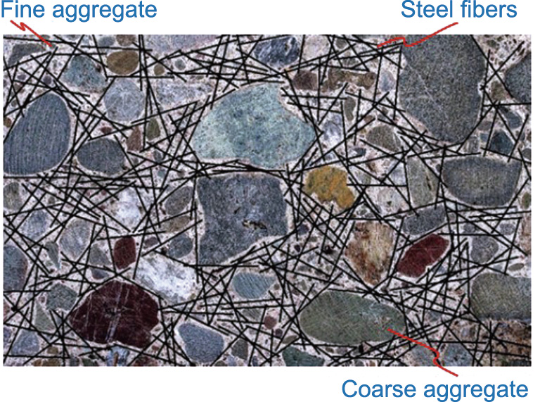
Fig. 2. Steel fibers randomly dispersed in SFRC. Reproduced from Ref. [1] with permission.
Xu et al. [20] found that the addition of steel fibers in concrete with the volume fraction of 20–50 kg·m–3 could significantly improve the static properties of a concrete mixture, such as flexural strength, tensile strength, shear resistance, spalling resistance, and abrasion resistance. Since Suaris and Shah [21] reported that the dynamic performances of FRC could be enhanced by means of steel fibers, and numerous experimental techniques have been adopted to investigate the dynamic responses of SFRC. For instance, many researchers [22–24] have investigated the effect of fiber content on the fracture properties of SFRC and have concluded that the flexural strength and pullout strength can be basically enhanced with the increase of fiber volume content. Li et al. [25] compared the flexural properties and the acoustic emission behaviors of SFRC including different fiber types (e.g., straight, hooked-end, and corrugated fibers). For a given fiber content, the hooked-end SFRC showed greater flexural strengths and acoustic emission values than the other two types of SFRC and the plain concrete. Cao and Yu [26] tested the pullout strengths of hookedend fibers embedded in concrete with different inclination angles and lengths. It was observed that the peak pullout strength of fiber in concrete matrix was associated with many factors, such as the fiber type, the embedded inclination angle and length, and the fiber diameter. Considering the effect of fiber orientation in concrete, Yoo and Banthia [19] comprehensively investigated the impact tensile—and flexural performances of SFRC. It was found that the SFRC would obtain better impact tensile strength when more fibers were aligned in the tensile load direction. Mindess and Zhang [27] studied the dynamic compressive failure modes of SFRC using dropping weights, it was found that owing to the mechanical properties of fiber, the mass and height of dropping weight were the main influencing factors of the failure mode of SFRC. Through a large number of split Hopkinson pressure bar (SHPB) tests [9,28– 30], an obvious strain rate hardening effect could be observed in SFRC. However, Wang et al. [31] and Mansur et al. [32] found that the influence of the increasing fiber content was more notable for the enhancement of concrete ductility than the compressive strength, which consequently reduces the brittleness and improves the tensile capabilities of concrete.
Owing to the limitation of experimental techniques and cost existing in dynamic and blast tests for SFRC, it is hard and impractical to fully study the dynamic behaviors and failure mechanism of SFRC only by means of large amounts of experimentation. Hence, numerical simulation is considered as an efficient approach to investigate the dynamic response and damage mechanism of SFRC. Taking the heterogeneity of SFRC into account, the general homogeneous model that assumes SFRC as a homogeneity [33– 37] cannot realistically reflect the randomly oriented and distributed steel fibers in concrete matrix. In a comparison, the mesoscale model that assumes concrete to be a three-phase composite (i.e., aggregate, mortar, and ITZ) has proved to be reliable in simulating the static and dynamic behaviors of different concrete materials [38–42]. Accordingly, the mesoscale modeling approach can be employed to establish a realistic computation model for investigating the bridging effect of steel fibers in the concrete mixture under static and dynamic loadings.
During the past two decades, massive mesoscopic investigations have been performed to simulate and predict the experimental tests of SFRC under impacts and blasts. Li et al. [37] simulated the dynamic responses of SFRC slab under free air explosion and contact explosion using the mesoscale modeling method. They reproduced the failure processes and the ultimate failure patterns of SFRC slab, and analyzed its blast resistance capabilities by comparing with the previous test results. Liu et al. [43] employed a homogeneous model to investigate the anti-projectile projection behavior of SFRC with the compressive strength of 90–190 MPa. They also conducted uniaxial compressive and four-point bending simulations to validate the mesoscale model for SFRC. Xu et al. [20,44] developed a two-dimensional (2D) mesoscale model consisting of hooked-end/spiral fibers, aggregates, and a mortar matrix to model the SFRC subjected to impact compressive/tensile loading at different strain rates. The effects of fiber fraction and the fiber shape on the dynamic increase factor (DIF) and the failure mechanism of SFRC were revealed. Moreover, to obtain a better simulation and understanding of the dynamic material properties and failure mechanisms of SFRC, various three-dimensional (3D) mesoscale models have been proposed by many investigators [45,46], where different phase components such as fiber, aggregate, and cement mortar were included. In summary of the abovementioned publications on the numerical simulations of SFRC, various kinds of mesoscale models have been developed and utilized to study the dynamic properties of SFRC. Nevertheless, each of these models does has its own advantages and drawbacks associated with various influencing factors (i.e., fiber/aggregate shape, model dimensions (2D/3D), and material models). Consequently, a comprehensive review of the state-of-art mesoscopic simulations is desirable to provide further insights into the investigation and development of SFRC subjected to impact and dynamic loading conditions.
The aim of this paper is to review the state-of-the-art mesoscopic works on the dynamic behaviors of SFRC; the overall contents are addressed as follows: ① a development of mesoscale model for SFRC; ② the generation of fiber in concrete mixture; ③ the contact algorithm between steel fiber and concrete mixture; ④ general material models for SFRC components (i.e., steel fiber, aggregate, and cement mortar); and ⑤ mesoscopic modeling applications of SFRC under impact and blast loadings. The emphasis of the mesoscopic applications was placed on the 3D mesoscale models for SFRC as compared to other mesoscale models, indicating our developed 3D mesoscale model has relatively high reliability in simulating the material behaviors of SFRC under impact and blast loadings. Finally, some problems in the existing mesoscopic models are proposed, which gives guidance for the further development of a mesoscopic modeling approach for SFRC.
《2. Generation of mesoscopic model for FRC》
2. Generation of mesoscopic model for FRC
As we illustrated earlier, the inclusion of fibrous materials in concrete can exhibit notable role in enhancing the mechanical properties of FRC, such as shear strength, tensile strength, and the energy absorption capability. For better understanding the mesoscale structure of FRC and capturing its failure mechanism, researchers have developed many mesoscale model frameworks with the explicit simulation for various types of fibers randomly distributed in FRC [4–18,27,28]. In this section, the development and application of the mesoscale models for FRC containing different fibers are summarized in detail. A series of typical mesoscale models are exemplified and compared with each other, while the emphasis was still placed on the blast and impact properties of FRC using mesoscale modeling approach.
《2.1. Development of mesoscale models for FRC》
2.1. Development of mesoscale models for FRC
Similar to the generation method of aggregate concrete, two methods have been employed for modeling the mesoscopic structure of FRC. The first one is the image processing method by means of X-ray computed tomography (XCT), which enables us to generate a reliable mesoscopic structural model of FRC. Employing the micro XCT with high resolution, the internal structure of different fiber reinforced materials has been characterized, including the glass fibrous material [47], the carbon fiber composite [48], and the steel fiber reinforced material [8]. Subsequently, many finite element simulations on the fibrous materials have been conducted using corresponding XCT-based mesoscale models. Qsymah et al. [49] adopted a two-scale homogenization approach to obtain the finite element model (FEM) of SFRC consisting of mortar, steel fiber, and pores, as shown in Fig. 3(a). Suuronen et al. [50] presented a technique to measure the orientation of steel fibers distributed in SFRC. As exhibited in Fig. 3(b), it can be found that fibers were mostly horizontally and vertically oriented in the specimen center and edge region, respectively. The identification of the fiber orientation has great potential for studying the meso-structural structure of FRC. Ponikiewski et al. [51] also employed the XCT method to explore the fiber volume and dispersion in an FRC wall (Fig. 3(c)), and held the view that the mechanical properties of FRC are associated with the volume, dispersion, and length of steel fibers included in concrete. However, it is both computationally costly and timeconsuming to conduct XCT-related measuring and modeling, which are also limited by the precision of XCT devices and computers.
《Fig. 3》

Fig. 3. FRC models obtained from XCT. (a) A three-phase SFRC mesoscale model consisting of mortar, steel fiber, and pores. Reproduced from Ref. [49] with permission. (b) A 3D SFRC mesoscale model considering the orientation of steel fibers. Reproduced from Ref. [50] with permission. (c) A 3D mesoscale model for an FRC wall. Reproduced from Ref. [51] with permission.
An alternative method is to establish some random line or solid elements to represent the fiber models in concrete. Based on the developed 2D and 3D mesoscale models of concrete, the fiber model has been assumed to be another phase and distributed among the mortar matrix phase. Xu et al. [20] proposed a 2D axisymmetric SFRC model consisting of aggregates, fibers, and mortar to modeling the dynamic compressive properties of SFRC, in which circular aggregates and hook-end fibers (Fig. 4(a)) are included. Using the 2D mesoscale model, the effects of fiber dosage and distribution on the strength and failure patterns of SFRC under dynamic compression loadings were investigated. As an extension of the mesoscale model in the previous literature [20], Xu et al. [44] developed a tri-phase mesoscale model to simulate the dynamic tensile behaviors of SFRC, where the aggregates, spiral fibers, and mortar matrix are included. The 2D notched cylinder models containing circular aggregates and the hook-end and spiral fibers were established as shown in Fig. 4(b). Additionally, the effects of fiber shape and dosage on the tensile properties of FRC were numerically analyzed and discussed in terms of the DIF, the energy absorption capability, and crack opening velocity of SFRC samples.
《Fig. 4》
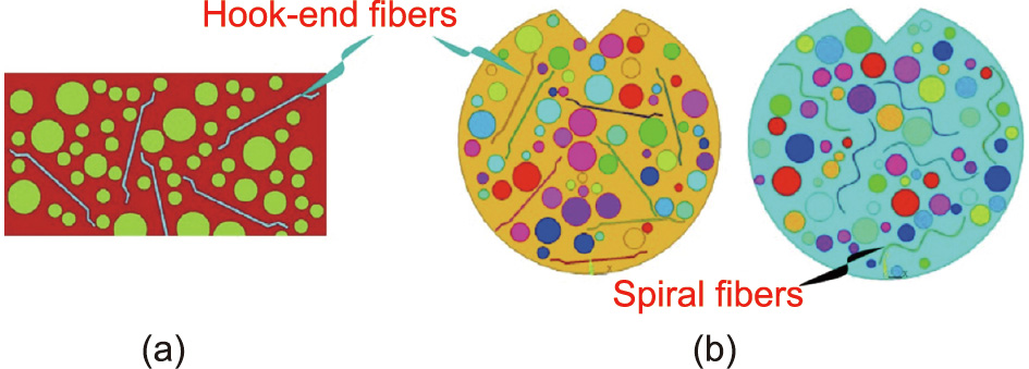
Fig. 4. 2D mesoscale models for SFRC in literature. (a) A 2D mesoscale model consisting of hook-end fiber models in the literature. Reproduced from Ref. [20] with permission. (b) A 2D mesoscale model comprising of hook-end and spiral fiber models in the literature. Reproduced from Ref. [44] with permission.
However, the abovementioned FRC models are mostly 2D models that cannot realistically reflect the actual dispersion characteristics of fibers in concrete, such as orientation, intersection, and parallel relationships. Accordingly, it is essential to develop highly efficient 3D mesoscale models to describe the stochastic distribution of fibers in concrete. Along with the development of computer technology, many 3D mesoscale FRC models [45,52–57] have gradually been proposed and employed to study the mechanical properties of fibrous material consisting of different types of fibers. Zhang [52] developed a 3D SFRC mesoscale model consisting of hook-end fibers, spherical aggregates, mortar, and ITZ between aggregates and mortar, as shown in Fig. 5(a). The dynamic compressive responses of SRFC at different strain rates were simulated, and the reliability of the proposed 3D model was verified according to the available SHPB test results. The aggregates in Zhang’s FRC model [52] are represented by spheres, which has limitations in reflecting the irregular characteristics of actual aggregates. Regarding the irregular shape and rough texture of realistic aggregates in concrete, Zhang et al. [53] developed a series of algorithms to generate a 3D mesoscale FRC model (Fig. 5(b)) that includes irregular shaped aggregates with rough texture and fibers with different lengths and shapes. Besides, the two regimes of the ITZ region between aggregate/fiber and mortar in FRC were well exhibited, which gives a promising tool in predicting the volume fraction of ITZ in concrete. Employing this model, the elastic modulus of FRC was also predicted and validated using the experimental data in literature [54]. Naderi and Zhang [55] also presented a 3D fourphase mesoscale model for SFRC consisting of realistic-shaped aggregates, fibers with different types and dimensions, mortar, and ITZ between aggregate and mortar, as exhibited in Fig. 5(c). Three type of fibers (i.e., straight, hook-end, and spiral fibers) were generated using the one-dimensional (1D) and 3D solid elements in this model. Owing to the realistic characterization of aggregates and fiber in SFRC, the mesoscale model has high feasibility in evaluating the elastic modulus of SFRC.
《Fig. 5》

Fig. 5. 3D mesoscale models for SFRC in literature. (a) A 3D SFRC mesoscale model consisting of hook-end fibers, spherical aggregates, mortar, and ITZ between aggregates and mortar. Reproduced from Ref. [52] with permission. (b) A 3D mesoscale FRC model including irregular shaped aggregates with rough texture and fibers. Reproduced from Ref. [53] with permission. (c) A 3D four-phase mesoscale model for SFRC consisting of realistic-shaped aggregates. Reproduced from Ref. [55] with permission.
Actually, the mechanical properties of concrete are significantly influenced by the heterogeneities caused by different inclusions, namely aggregates, cement paste, micro-pores, and initial flaws. Thereby, the addition of fibers with random distribution in concrete also improves the heterogeneity of fibrous composite, making it difficult to capture the action mechanism of fibers on the mechanics of FRC, particularly for those blast and impact conditions. It has been found from experimental results that the bonding strength between fibers and cement paste is one of the most significant factors for enhancing the dynamic properties of FRC. Therefore, the effect of fiber on the material properties of FRC has been performed using the 3D mesoscale models containing fibers and homogeneous continuum cement matrix [56,57]. In our previous researches [45], we proposed a 3D mesoscale model comprising of two-phase components (i.e., concrete matrix and straight fibers) to investigate the static and dynamic responses of SFRC, as shown in Fig. 6(a). As for the bonding and sliding interactions between steel fibers and concrete matrix, which was defined by a contact algorithm in the hydrocode LS-DYNA. Then the dynamic compressive and tensile simulations of SFRC under high strain rate loadings were simulated using the 3D mesoscale modeling approach. Further simulations on the contact detonation of SFRC have been also numerically studied and compared with existing test results, which would be summarized in the following example applications (Section 4). Our proposed numerical modeling approach has proved to have high fidelity in simulating the dynamic responses of SFRC, and it has been further followed and employed by many other researchers in further investigations of SFRC. For instance, Su et al. [58] developed a 3D two-phase mesoscale model consisting of steel fibers and concrete matrix (Fig. 6(b)) to characterize the ultra-high performance steel fiber reinforced concrete (UHPSFRC). Whilst the ITZ effect between fiber and concrete was investigated by the single fiber pullout strength, which was selected to describe the bond–slip behavior between fiber and concrete matrix. Subsequently, based on the 3D mesoscale model, the dynamic splitting-tensile behaviors of UHPSFRC were simulated through SHPB simulations. Liang and Wu [46] developed the same 3D SFRC model as that in Fig. 6(c) to explore the effects of fiber content and aspect ratio on the mechanical properties of FRC under various loading conditions, namely compression, flexural tension, and splitting tension. Recently, Wu et al. [59] and Zhao et al. [60] employed similar mesoscale models as that in the literature [45] to investigate the mechanical properties of SFRC under dynamic splitting-tensile and uniaxial compressive loadings at different strain rates. Based on the verified mesoscale model, the effects of fiber content and aspect ratio, specimen shape and size, and strain rate on the dynamic behaviors of SFRC were numerically studied. Finally, they also proposed and validated the dynamic constitutive relationships of SFRC to predict the dynamic tensile and compressive strength as a function of strain rate and fiber content. Additionally, Shu et al. [61] developed a 3D finite element model (Fig. 6(d)) to reflect the realistic mesoscopic structure of SFRC structure using the ABAQUS software. Thereafter, they employed this mesoscale model to simulate the SFRC beam four-point bending test with consideration of the effects of fiber volume fraction and fiber corrosion. They finally calculated the optimum fiber fraction (2%) for the best bending resistance, and quantitatively described how does the steel fiber corrosion affect the mechanical responses of SFRC structure.
《Fig. 6》

Fig. 6. 3D mesoscale models of ultra-high performance concrete (UHPC) consisting of fibers and concrete matrix. (a) A 3D mesoscale model comprising of two two-phase components (i.e., concrete matrix and straight fibers). Reproduced from Ref. [45] with permission. (b) A 3D two-phase mesoscale model consisting of steel fibers and concrete matrix in the literature. Reproduced from Ref. [58] with permission. (c) A 3D mesoscale model for simulating SFRC in the literature. Reproduced from Ref. [46] with permission. (d) A 3D mesoscale model for the SFRC beam in the literature. Reproduced from Ref. [61] with permission.
《2.2. Generation of fibers》
2.2. Generation of fibers
In this section, the generation of fiber models and corresponding contact algorithm between fiber and concrete or mortar matrix are reviewed as follows. Xu et al. [44] employed a Matlab program to generate steel fiber models with random positions and orientations, and then these fibers were placed in 2D cylinder specimen (Fig. 7(a)) until the pre-defined fiber content was achieved. The method on how to determine the shape of hooked-end and spiral fibers in concrete is not described in this work.
In Naderi and Zhang’s simulations [55], three types of fibers were generated based on the Delaunay triangulation strategy and the Voronoi tessellation method. First, the straight fiber with the circular cross-section made by a 1D element was generated by controlling fiber generator points passing through the centers of Voronoi cells. Based on the generation method of straight fiber, the hooked-end and helix fibers were generated separately. Note that the helix fiber was generated by turning around a vector at a constant distance and moving parallel to the axis, while the axis was randomly generated in the spatial domain of aimed specimen model. The generation process of these fibers is schematically exhibited in Fig. 7(b).
Zhang et al. [53] employed Euclidean geometry algorithm to generate the linear and hooked fibers as shown in Fig. 7(c). They selected two parameters, fiber length and radius, to control the shape of linear steel fiber, while three different length parameters and fiber radius are required to characterize the hooked fibers. They also attempted to mix the linear and hooked fibers together in a concrete specimen to simulate the SFRC containing different fibers, shown in Fig. 7(c). Han et al. [62,63] also presented a novel 3D numerical framework including helix and circuitous geometry models, to model those randomly dispersed and aggregated carbon nanotubes in polymer composites. The interphase regions between inclusions and matrix are also considered in the developed modeling framework. However, corresponding computations on the physical and mechanical properties on the composite have not been performed using this model. It is worth using this modeling approach to simulate the dispersed and aggregated characteristics of short steel fibers in concrete, and further investigate the mesoscopic behaviors of SFRC with various volume fractions.
Fig. 7(d) presents the 3D mesoscale models for steel fibers randomly dispersed in a 3D SFRC models shown in Fig. 5(a) [52]. The length and volume content of these 3D straight fibers was set as 6 mm and 1%, respectively. These steel fibers were delivered in the cylinder specimen using the take-and-place algorithm [64], and their spatial locations were judged in contrast with the generated aggregate center (Fig. 5(a)). Finally, the generated steel fibers were randomly dispersed or embedded in mortar matrix and ITZ.
Yu et al. [65] and Han et al. [66] proposed an effective computer generation algorithm to generate a large number of ellipsoid particles to simulate the short fibers randomly distributed in a cubeshaped domain. They also developed a new compaction and selection algorithm to improve the grain volume fraction, where the fiber-volume fraction is up to 29.07%. They concluded the developed algorithm is more advanced than the conventional takeand-place algorithm. Similarly, Guan et al. [67] developed a multi-scale computational model to evaluate the mechanical properties of FRC, in which the disordered fibers are represented by the ellipsoid inclusions as Fig. 7(e). Through the simple shape assumption for fibers, the complex contact information between fibers could be avoided in the calculation. However, there is little or no application for the ellipsoid fibers in actual concrete engineering.
To simulate the corrosion behavior of steel fibers in SFRC, Shu et al. [61] selected two types of elements, truss elements and solid elements, to model the steel fibers, as shown in Fig. 7(f). They supposed the rust pits randomly occurred on the surface of solid element fibers, and the pit erosion parameters were referred to the available test data in the literature [68].
Considering the random distribution of fibers in concrete matrix, Zhang et al. [69] established the straight and hook-ended steel fibers with different contents, as shown in Fig. 7(g), to investigate the post-cracking tensile strength under different loading directions. Both the numerical and experimental results indicate that the tensile strength of SFRC specimen subjected to the load along the casting direction (Z-axis) is relatively greater than that along the other two axes.
《Fig. 7》
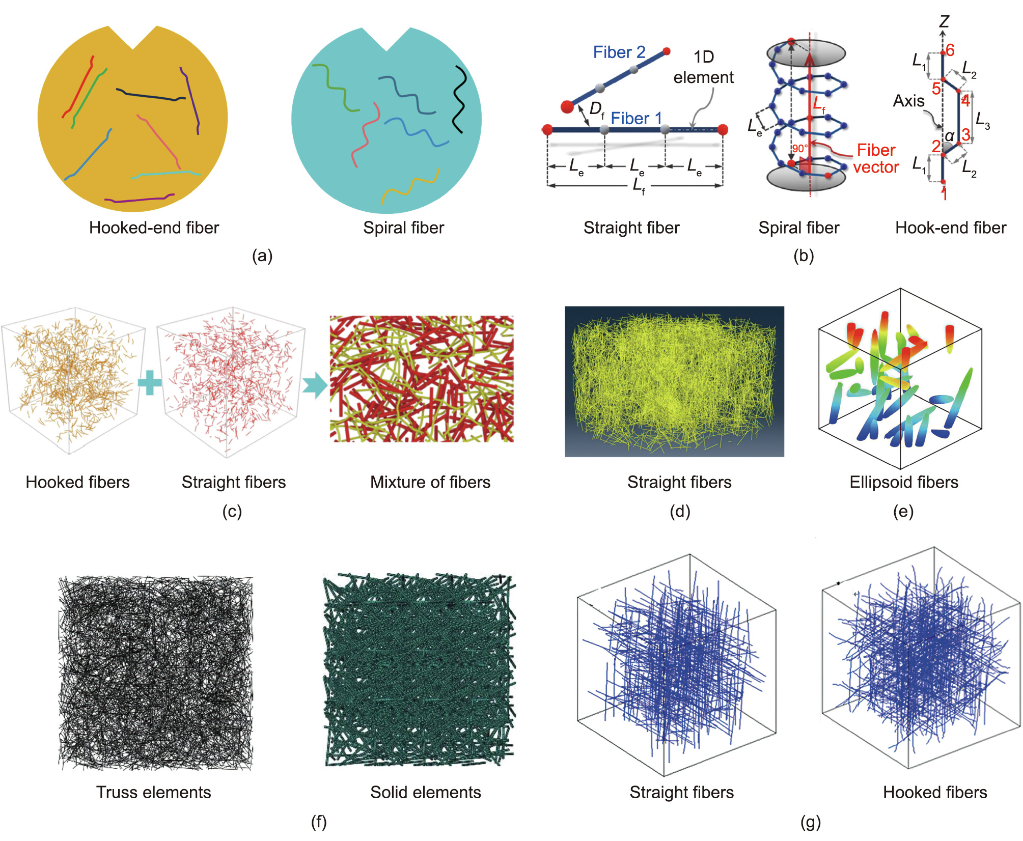
Fig. 7. Generation of fiber modes in hooked-end and spiral fibers. (a) Hooked-end and spiral fibers. Reproduced from Ref. [44] with permission. (b) Straight, spiral, and hooked-end fibers. Reproduced from Ref. [55] with permission. (c) Hooked and straight fibers in Zhang et al.’s study. Reproduced from Ref. [53] with permission. (d) Straight fiber models developed by Zhang R. Reproduced from Ref. [52] with permission. (e) Ellipsoid fibers. Reproduced from Ref. [67] with permission. (f) Straight fibers in Shu et al.’s study. Reproduced from Ref. [61] with permission. (g) Straight and hooked fiber models developed by Zhang S. et al. Reproduced from Ref. [69] with permission.
In the author’s earlier publication [45], a random distributed mesoscale framework was established to generate the 3D mesoscale model for SFRC consisting of straight round fibers and a homogenous concrete matrix, and a corresponding generation algorithm for these random distributed fibers in concrete is shown in Fig. 8. First, the mixed congruent algorithm was adopted to generate a random number list for determining the random positions of fibers. Thereafter, the fiber number was calculated by the ratio of total fiber volume to unit-fiber volume (V), wherein the former could be derived from fiber content (Vf) and the latter was defined as V = πD2 L/4, where D and L are the diameter and length of the fiber, respectively. In accordance with the generated random number list, the random orientation and location of fibers are controlled by Eqs. (1) and (2) [45]:

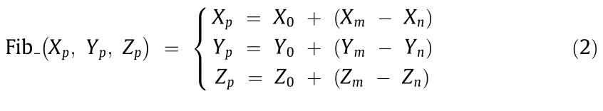
where Fib_ori and Fib_(Xp, Yp, Zp) are the orientation and spatial coordinates of fiber, respectively; α, β, and  are the rotation angle around X, Y, and Z axis, respectively; (X0, Y0, Z0) is the initial location coordinate of original fiber; (Xm, Ym, Zm) is the coordinate of middle point of original fiber; (Xn, Yn, Zn) is the coordinate of a random point in specimen domain.
《Fig. 8》

Fig. 8. Generation algorithm of straight fibers in author’s prior publication. Reproduced from Ref. [45] with permission.
Afterwards, in accordance with the above-determined orientation and location coordinates, the calculated fibers were delivered into the specimen one by one. During the placing process, the fibers were required to meet the limitation of specimen boundary and have no intersection with those delivered ones. Finally, after the aimed fiber content was achieved, corresponding position and orientation information of fibers will be output and recorded. Liang and Wu [46] and Su et al. [58] employed the similar generation method for the short-straight fibers and randomly placed them in SFRC specimen, as shown in Figs. 6(b) and (c).
《2.3. Generation of coarse aggregate model》
2.3. Generation of coarse aggregate model
As illustrated in the above sections, some mesoscale models for SFRC are two-phase models comprising of fibers and mortar matrix, while some are three-phase models considering the coarse aggregate inclusions. In this section, the mesoscopic configurations and characteristics of general aggregate models in mesoscale models for FRC are introduced as follows.
After the 2D fibers were placed in the specimen plane, Xu et al. [44] established circular aggregate models (Fig. 9(a)) to represent the coarse aggregates in the concrete specimen. The particle size and content of the aggregate models were determined by the Fuller grading curve [70], and they were randomly placed into the specimen using the take-and-place algorithm one by one. Similarly, Jin et al. [71] assumed coarse aggregates to be circular in the mesoscale model (Fig. 9(b)), wherein a thick layer (1 mm) around the circular aggregate was generated for representing the ITZ layer. Two graded aggregates (12 and 30 mm) were adopted to simulate the random aggregate gradation, which is different from Xu et al.’s work [20,44]. Furthermore, Zhang [52] attempted to establish a 3D cylinder model to represent the SFRC specimen, in which the coarse aggregates are modeled by the spheres with random characteristics in size and distribution, as shown in Fig. 9(c). These aggregate particles were randomly distributed in mortar matrix by means of the same method as Jin et al.’s [71] simulation, and the ITZ layers were also involved between these aggregates and mortar matrix.
《Fig. 9》
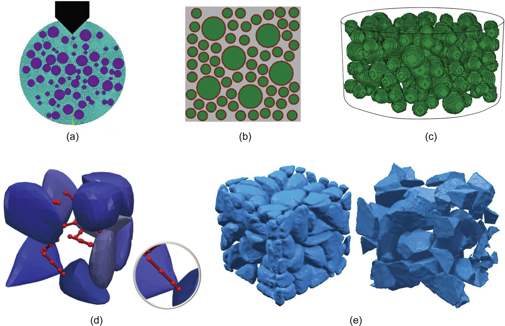
Fig. 9. Mesoscopic models for aggregates in FRC: (a) Circular aggregate models in a 2D two-phase model. Reproduced from Ref. [44] with permission. (b) circular aggregate models in a 2D three-phase model. Reproduced from Ref. [71] with permission. (c) 3D spherical aggregate models. Reproduced from Ref. [52] with permission. (d) 3D realistic shaped aggregates. Reproduced from Ref. [55] with permission. (e) 3D irregular-shaped aggregate models. Reproduced from Ref. [53] with permission.
It is well known that the aggregates used in actual concrete engineering are usually gravel or crushed aggregates with random shapes, such as a rough surface texture and sharp corners and edges. Therefore, the abovementioned circular and sphere particles cannot explicitly present the actual shapes of aggregates in concrete, and have limitations in describing the local and overall stress–strain condition of concrete in simulations [72,73]. Thus, apart from the regular aggregate particles [20,44,70,71,74], a large quantities of irregular particle models with random shape characteristics have been established for the simulation of aggregates in concrete [75–81].
However, owing to the coexistence of fibers and random aggregates in the 3D mesoscale models, mightily increases the grid number and reduces the computation efficiency. Thus, few publications have been reported on the 3D mesoscale models for SFRC with fibers and random aggregates involved in the mortar matrix. As the computer technology and computation algorithm advances by leaps and bounds, some researchers developed efficient modeling approach for the SFRC containing four phases, namely mortar matrix, steel fibers, random aggregates, and ITZ. For instance, Naderi and Zhang [55] used the Voronoi tessellation method to add the random coarse aggregate particles into the fibrous model, as shown in Fig. 5(c). Whilst, these random particles (Fig. 9(d)) were generated based on the Voronoi cells selecting the fiber endpoints as seed points. Note that Fig. 9(d) exemplifies the particle insertion into straight fibers, and it can be broadened for the spiral or hook-ended fibers based on the similar method. Also, to obtain realistic aggregate models, Zhang et al. [53] combined cell fracture algorithm [82], Catmull–Clark subdivision algorithm [83], displacement mapping, and Laplace smoothing algorithm in the aggregate generation process. Firstly, low-polygon aggregates with convex shapes were generated using the cell-fracture algorithm. Secondly, the Catmull–Clark subdivision algorithm was used to smooth the aggregates by iterations, and the aggregates with smooth surfaces could be obtained. Finally, the displacement mapping and the Laplace smoothing algorithm were employed to construct the aggregates with rough surface texture. As shown in Fig. 9 (e), the gravel-like and crushed stone-like aggregates are generated by the Laplace smoothing subdivision and the simple Catmull– Clark subdivision, respectively.
《3. Material models for FRC》
3. Material models for FRC
For the attempt to perform the FEM computation of FRC under different loadings using the abovementioned mesoscale models, appropriate material models must be used to define the mechanical properties of each ingredient, for example, fiber, mortar matrix, aggregate, and ITZ. Herein, general material models previously employed in the SFRC models are summarized as follows.
《3.1. Material models for steel fibers》
3.1. Material models for steel fibers
In Xu et al.’s mesoscale modeling investigations [44], the hooked-end and spiral steel fibers were modeled by the MAT_PIE CEWISE_LINEAR_PLASTICITY material model (Mat_24) in LS-DYNA, where the non-linear softening behaviors of fibers were described in terms of the effective stress and the effective plastic strain, and the strain rate effect was also taken into account through the hardening parameter for the yield stress of material. The main model parameters for Mat_24 in LS-DYNA include: the mass density of fiber, Young’s modulus, Poisson’s ratio, and yield stress. Naderi and Zhang [55] investigated the effect of fiber content on the elastic modulus of FRC using their proposed fourphase mesoscale model, in which all the components are assumed to be linearly elastic materials described by the elastic modulus and Poisson’s ratio. In addition, Zhang et al. [53] studied the Young’s modulus of ultra-high performance concrete (UHPC) containing short and long fibers by the mesoscale modeling approach that considers fiber as elastic and isotropic material, and it was found that the maximum elastic modulus could be reached when the volume content of short and long fibers was set as 1.5% and 0.5%, respectively, which is relatively lower than the experimental results and was attributed to the inaccurate assumption of ITZ thickness in the modeling approach. Liang and Wu [46], Peng et al. [84], and Su et al. [58] employed the MAT_PLASTIC_KINEMATIC Mat_Plastic_Kinematic material model (Mat_98) in LSDYNA to model the steel fibers as truss elements to improve the computation accuracy and efficiency of SFRC under quasi-static and dynamic loadings, and the corresponding model parameters were material density, elastic modulus, Poisson’s ratio, and yield stress. Zhang et al. [69] adopted the elastic–plastic model for the constitutive model of steel fiber. Based on the available test results in literature [85], they set the initial and ultimate yield strength, and corresponding plastic strain of steel fibers. Zhang [52] and Jin et al. [71] utilized the bilinear constitutive model to describe the mechanical responses of steel fiber, wherein an elastic segment and a hardening segment are included in the constitutive model. The hardening modulus of steel fiber was set as 1% of the initial elastic modulus.
In the author’s previous simulations [45], the material characters of steel fiber under high-rate loading were described using the Johnson–Cook (JC) material model (Mat_15) in LS-DYNA, which is applicable for simulating metal materials at high strain rates. Both the material stress and strain with consideration of the fracture damage of material were taken into account in the JC material model, and the corresponding material parameters include the damage parameters, shear modulus, temperature parameter, specific heat, Poisson’s ratio, and mass density. To investigate the effect of fiber content on the dynamic properties of SFRC, a series of mesoscopic simulations of dynamic compression, dynamic tension, and contact detonation have been performed, which will be briefly reviewed in the following section to illustrate the rationality of our previously proposed 3D two-phase mesoscale modeling approach.
《3.2. Material models for coarse aggregates》
3.2. Material models for coarse aggregates
To describe the mesoscopic characteristic of coarse aggregates in the SFRC model, various material models have been utilized in mesoscale modeling. Jin et al. [71] assumed coarse aggregates to be brittle materials and employed the idea of an elastoplastic constitutive model to describe the mechanical behaviors of coarse aggregates in SFRC. Naderi and Zhang [55] assumed the aggregates to be linearly elastic in their mesoscale model, and the elastic modulus was the main model parameter for aggregates. Xu et al. [20,44] used PSEUDO_TENSOR (Mat_16) in LS-DYNA to model aggregates in mesoscopic simulations, in which the DIFs of aggregates were determined by the existing test results of rock material [86,87].
According to the aforementioned material models for coarse aggregates in SFRC, it can be learned that most investigators assumed aggregates to be linearly elastic materials and neglected the plastic behaviors of aggregates under dynamic loadings. Based on the literature [88–91], it can be learned that the elastic material assumption for aggregates is only applicable or reasonable when concrete is under quasi-static loading, but it will show obviously non-linear characteristics under dynamic loading conditions. Therefore, to give a relatively precise simulation for the aggregates in SFRC under dynamic loadings, the material models with considerations of the strain rate effect and material plasticity of aggregates (i.e., the Holmquist–Johnson–Cook (HJC) model [81], modified Drucker–Prager/cap plasticity model [92], continuous surface cap model [88], and CONCRETE_DAMAGE_REL3 (Mat_072R3) in LS-DYNA (K&C model) [93–95]) should be employed in the abovementioned SFRC models.
《3.3. Material models for mortar matrix》
3.3. Material models for mortar matrix
To more realistically simulate the complex behaviors of mortar matrix under dynamic loadings, different constitutive models have also been employed in the aforementioned models. Xu et al. [20] first adopted a plasticity model named PSEUDO_TENSOR (Mat_16) in LS-DYNA to simulate the mortar phase in SFRC under dynamic compression loading. This model comprises two failure surfaces to describe material strength variation and damage behavior. Further, based on the Mat_16 in LS-DYNA, the K&C model consisting of three failure surfaces was employed to simulate the material properties of mortar matrix in SFRC under dynamic tension, according to Xu et al.’s other work [44]. Peng et al. [84] utilized the MAT_BRITLE_DAMAGE (MAT_096) model in LS-DYNA, an anisotropic brittle damage model for brittle material, to simulate the properties of mortar matrix. Three damage surfaces are included in this model to describe the material damage degradation, and the strain rate effect is also considered based on the viscosity theory. Fang and Zhang [45] employed the HJC model to simulate the mortar matrix in SFRC under contact explosion. In this material model, the material strength is considered as a function of pressure, strain rate, and damage, and the pressure can be expressed as a function of volumetric strain considering the permanent crushing. Besides, many researchers [46,58–60] have adopted the K&C material model to simulate the matrix in SFRC under static and dynamic loadings. Three basic model parameters, that is, density, unconfined compressive strength, and Poisson’s ratio, should be input as the basic parameters in this model, while other parameters should be automatically calculated and generated based on these basic parameters. Also, these automatic generated parameters can be examined and modified by the user. In summary, with a comprehensive consideration of calculation accuracy, efficiency, and convenience for mesoscale modeling, a more reasonable material model should be adopted to simulate the SFRC matrix at high strain rates.
《3.4. Interfacial relationship in SFRC》
3.4. Interfacial relationship in SFRC
As we introduced in Section 2, SFRC has been modeled as a two-, three-, or four-phase composite composed of fiber, mortar matrix, aggregate, and ITZ between fiber/aggregate and the matrix. It has been acknowledged that the ITZ significantly influences the mechanical properties of concrete [72,96] owing to its weak and heterogeneous properties in concrete. Moreover, considering the fiber-bridging effect contributed by the steel fibers randomly dispersed in SFRC, the fiber–matrix interfacial relationship is the foundation to analyze the mechanical properties of SFRC. The fiber pullout test has been generally performed to investigate the bond– slip relationship between fiber and matrix by many researchers [97–100]. Based on the previous experimental works, it has been acknowledged that the pullout results of single fiber embedded in matrix are dependent on many factors, namely the fiber shape [101,102], fiber surface treatment [103–106], inclination angle [107–111], embedded length [112–117], pullout rate, and matrix property [118,119]. Particularly, with reference to many pullout tests of fiber embedded in different types of matrices, it was found that the mechanical characteristics of steel fibers embedded in UHPC matrix with smaller water-to-cement ratio differed remarkably from those in normal concrete or high strength concrete [120– 123]. Fig. 10 shows the pullout stress–slip curves of short straight fibers embedded in normal concrete and UHPC matrix. It can be observed that the debonding behaviors of steel fibers in normal concrete occurred immediately after reaching the peak stress, while the pullout stress of the same steel fibers in UHPC matrix declined continuously as the slip increased. As demonstrated by the microstructure characteristics of fiber interfacial zone in UHPC matrix and concrete, the ITZ between fibers and matrix in the former was much denser than the latter. Thus, many interfaceenhancing technologies have been employed to improve the adhesion between steel fibers and concrete matrix by means of high strength matrices and/or modifying the matrix [108,119,124]. In contrast, Bindiganavile and Banthia [125] found that the bond–slip response between fiber and matrix was also significantly affected by the fiber modulus. For instance, a higher stiffness appeared at the pre-peak pullout curve of the interface between matrix and low-modulus fiber. Owing to the viscoelastic response of the interface, the SFRC matrix with higher energy absorption capacity or toughness could be obtained by using low-modulus steel fiber. Furthermore, it has been demonstrated in literature [126,127] that the structural toughness of SFRC is dependent on the bond–slip behavior between fiber and the matrix. Bindiganavile and Banthia [126] reported that the toughness difference between SFRC and other types of FRC incorporating polymer fibers would be diminished at higher loading rates, which is mainly because the bond–slip behavior of the latter was efficiently improved depending on the visco–elastic nature of polymer fibers. Besides, they reported that the pullout energy of steel fibers was improved with increasing loading rates. However, an obvious decreasing tendency occurred on the toughness of the SFRC at a high loading rate, with a cracking opening displacement rate of 3000 m·s–1 , which is because of the fracture failure of fiber. Banthia and Trottier [128] commented that the energy absorption capability of SFRC was also related with the fiber shape, and the deformed steel fibers embedded in cement matrix exhibited higher pullout resistance as compared to flatend fibers.
《Fig. 10》

Fig. 10. Pullout stress–slip of straight fibers in normal concrete and the UHPC matrix. Reproduced from Refs. [121,122] with permission.
In summary, one of the points of mesoscale modeling for SFRC is how to reasonably describe the interfacial relationships between the fiber/aggregate and matrix, which is extremely associated with the simulation results for SFRC under various loading conditions. Generally, two types of methods have been developed and employed to model the bonding relationship between the fiber and concrete matrix, that is, the explicit simulation of ITZ as an annular region around fiber and the implicit contact algorithm describing the interfacial relationship between fiber and concrete matrix. Actually, it can be observed from the experimental results [129] (Fig. 11(a)) that an annular region with certain thickness does exist between the fiber and concrete, namely the ITZ region. Based on the scaling algorithm employed in Zhang et al.’s simulation [53], the ITZ region with a thickness of t around fiber was simulated as Fig. 11(b), which was defined by corresponding material models to describe the interfacial relationship between the fiber and concrete matrix. However, owing to the enormous number of fiber in concrete, this explicit simulation for ITZ between fiber and concrete matrix is confronted with increasing difficulties in the finite element meshing and computational efforts. Thus far, three different contact algorithms (i.e., the same node assumption [60,61], 1D contact algorithm (Contact_1D model) in LS-DYNA [45,46], and coupling algorithm [39,84,130]) have been developed and employed to describe the bonding relationship between the fiber and matrix, which is based on the results of single fiber pullout data. In the case of the pullout test for a smooth fiber with round cross-section, the relation between pullout load versus the slip displacement along fiber length is exhibited as shown in Fig. 12. Observed from Fig. 12, the pullout process of smooth fiber embedded in the concrete matrix can be divided into three sections: The pullout load shows a linear increasing trend (see line OA) firstly. Then the cracking initiated at the ITZ region when the external load beyond the critical value (Pcrit) and continued to propagate in the AB section. Once the maximum load (Pmax) was reached, the fiber embedded in matrix remained the minimum length and it was fully debonded from concrete matrix at the point C. After that, the fraction phase purely controlled by the fractional force between debonding fiber and concrete matrix. According to the above-illustrated working mechanism of fiber under pullout tension, the 1D contact algorithm Conatct_1D in LS-DYNA has been employed by many researchers to interpret the bonding, debonding, and sliding behavior of steel fibers in concrete matrix, and the detailed introduction of this algorithm can be referred to literature [46,58]. However, considering the aforementioned property differences of fiber–matrix interface in concrete and UHPC matrix, the computational parameters of ITZ between the fiber and matrix should be determined depending on corresponding fiber-pullout test results.
《Fig. 11》
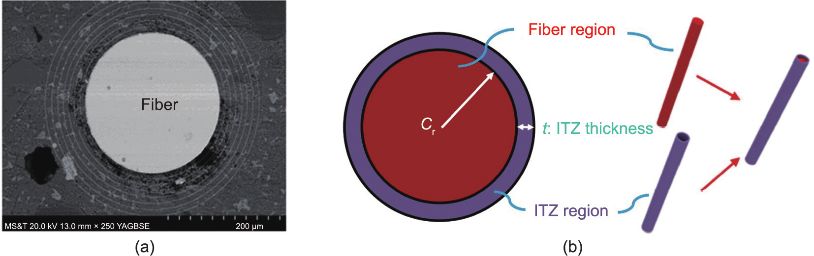
Fig. 11. ITZ around fiber and aggregate in FRC. (a) Back scattered election image of ITZ around fiber. Reproduced from Ref. [129] with permission. (b) Numerical ITZ around fiber. Reproduced from Ref. [53] with permission.
《Fig. 12》
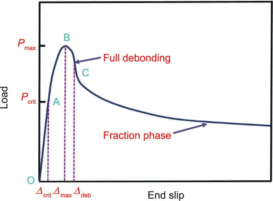
Fig. 12. Pullout load versus end slip curve of fiber embedded in concrete matrix. Reproduced from Ref. [58] with permission.
Besides, the interaction relationship between aggregate and mortar matrix in SFRC has also been considered by some scholars. In Zhang’s [52] and Jin et al.’s [71] simulation works, a thick layer (see the red region in Figs. 13(a) and (b)) around aggregate model was generated for the representation of the ITZ between aggregate and mortar matrix. They assumed ITZ to be a weakened mortar phase and adopted the damaged plasticity constitutive model [131] to describe the mechanical behaviors of mortar and ITZ in SFRC under dynamic compression. In this constitutive model, the mechanical responses of concrete are described by damaged plasticity, and the failure patterns are mainly exhibited in terms of the tensile and compressive cracks. Naderi and Zhang [55] utilized the modified scaling technique to generate the ITZ layer surrounding aggregate in the SFRC model. As shown in Fig. 13(c), the ITZ layer with a constant thickness (0.05 mm) was generated between the surfaces of original and scaled aggregates. The ITZ phase was assumed to be a linear elastic material characterized by three material parameters such as the Young’s modulus, Poisson’s ratio, and thickness. Similarly, Zhang et al. [53] adopted the same scaling algorithm as Naderi and Zhang [55] to obtain the ITZ phase of aggregates, as shown in Fig. 13(d). However, ITZ is a heterogeneous phase with porous microstructure and its mechanical properties cannot be described using the linear elastic constitutive model. To our best knowledge, many nonlinear and elastic–plastic constitutive models, such as K&C model [93,132,133] and concrete damage plasticity model (CDPM) [89], have been proved and used to characterize the mechanical responses of ITZ in normal concrete. Thus, it is suggested that the K&C and CDPM model can be adopted for ITZ description in the mesoscopic modeling of SFRC.
《Fig. 13》

Fig. 13. ITZ region between the aggregate and mortar matrix in the SFRC model. (a) ITZ in a 3D three-phase SFRC model. Reproduced from Ref. [52] with permission. (b) ITZ in a 2D four-phase model. Reproduced from Ref. [71] with permission. (c) ITZ around 3D irregular aggregates. Reproduced from Ref. [55] with permission. (d) ITZ around 3D aggregate models. Reproduced from Ref. [53] with permission.
《4. Mesoscopic analysis of SFRC under dynamic loading》
4. Mesoscopic analysis of SFRC under dynamic loading
Many mesoscopic efforts on the mechanical properties of SFRC under various high-rate loading (e.g., dynamic compression and tension, contact explosion, and projectile penetration) have been conducted in the literature [134–143]. The dynamic compressive strength, dynamic tensile strength, and blast and projectile penetration resistance of SFRC have been studied using different mesoscale modeling approaches. In this section, the mesoscopic results of SFRC using different mesoscale models are reviewed and compared with each other.
《4.1. Compressive properties of SFRC》
4.1. Compressive properties of SFRC
The dynamic compressive strength of SFRC has been extensively investigated in the past, and it has been generally suggested that the compressive strength is insignificantly affected by addition of steel fibers [134–137]. To investigate the work mechanism of steel fibers in SFRC under dynamic compression, some researchers have performed mesoscale simulation on the failure processes and patterns of SFRC [45,52,59,60]. Zhang [52] simulated the stress states of SFRC subjected to quasi-static and dynamic compression (Fig. 14). They found that the upright fibers in concrete mainly bore pressure stress, while the fibers lying on the horizontal plane mainly endured tensile stress. It was indicated that steel fibers can play an important role in enhancing the ductility and toughness of SFRC. Further, it can be also seen from Fig. 14 that the pressure stress of the steel fibers in the edge area was much higher than that in the center part, which indicates that the steel fiber bridging effect is effective in prevent concrete cracking under dynamic loadings. Zhao et al. [60] modeled the compressive failure process of SFRC with the volume content of 0.5% for steel fibers, as shown in Fig. 15. According to the variation tendency of stress– strain relation of SFRC, the stress state variation of steel fibers in concrete at different yield load, peak load, and failure load are exhibited as Figs. 15(a)–(c), respectively. From Fig. 15, it can be seen that the restraint behavior of steel fibers on concrete matrix would be enhanced as the loading process gradually went on. During the loading process, these steel fibers suffered from both compressive and tensile stress, which contributed to the restriction of incline cracks in concrete matrix. Similarly, Wu et al. [59] employed the 3D mesoscale modeling approach to simulate the SHPB test for SFRC under high-rate loadings (Fig. 16), they observed that the cracking failure mainly occurred at the specimen edge and the concrete fragment was bridged and connected with each other by the dispersed steel fibers, which is highly in line with the existing test results.
《Fig. 14》
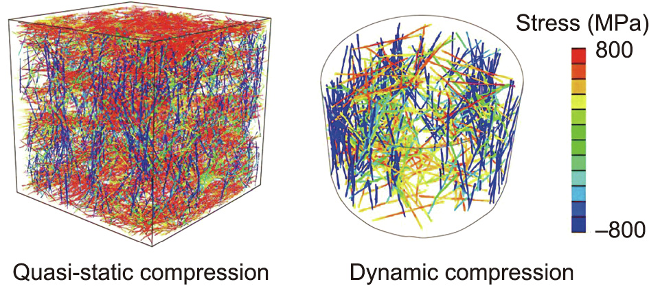
Fig. 14. Stress state of steel fibers in concrete under quasi-static and dynamic compression. Reproduced from Ref. [52] with permission.
《Fig. 15》
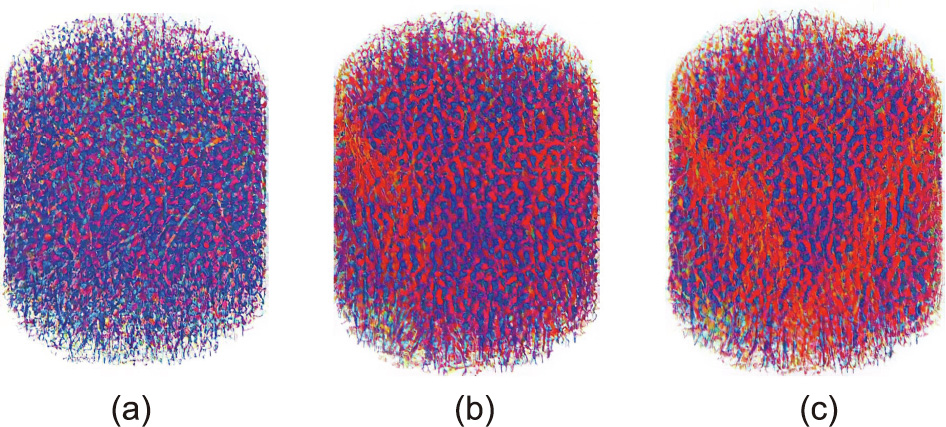
Fig. 15. Quasi-static compressive failure process of SFRC including 0.5% steel fibers at different load states: (a) yield load, (b) peak load, and (c) failure. Reproduced from Ref. [60] with permission.
《Fig. 16》
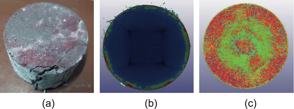
Fig. 16. Dynamic compressive failure patterns of SFRC: (a) test results; (b) simulation results for mortar matrix; and (c) simulation results for steel fibers. Reproduced from Refs. [59] with permission.
Furthermore, Fang and Zhang [45] also numerically investigated the strain rate ( ) effect on the compressive properties of SFRC using the 3D random mesoscale modeling approach (Fig. 8). Fig. 17(a) shows the compressive stress (σ)–strain (ε) curves of SFRC with 3% steel fibers at different strain rates. From Fig. 17(a), it can be found that the strain rate exhibited an insignificant enhancing effect on the peak stress of SFRC within the strain rate of 10–4 –200 s–1 , while the compressive stress was extensively enhanced when the strain rate ranged from 200 to 500 s–1 . On the basis of dynamic compressive strength of SFRC at different strain rates, corresponding numerical DIF values were compared with the experimental data and Comité Euro–International du Béton (CEB) predictions in Fig. 17(b) [8,45,144–147]. As shown in Fig. 17(b), there was almost no different between the DIF of SFRC and plain concrete when the strain rate was below 60 s–1 , while the former was slightly bigger than the latter beyond the strain rate of 60 s–1 . In addition, it was found that the fiber content had little effect on the DIF of SFRC under a low strain rate, while the SFRC with lower fiber content tended to show higher DIF. In summary, the steel fiber cannot provide significant enhancement on the DIF of SFRC, and the DIF of SFRC can be usually represented by plain concrete under same strain rate [145,148].
《Fig. 17》
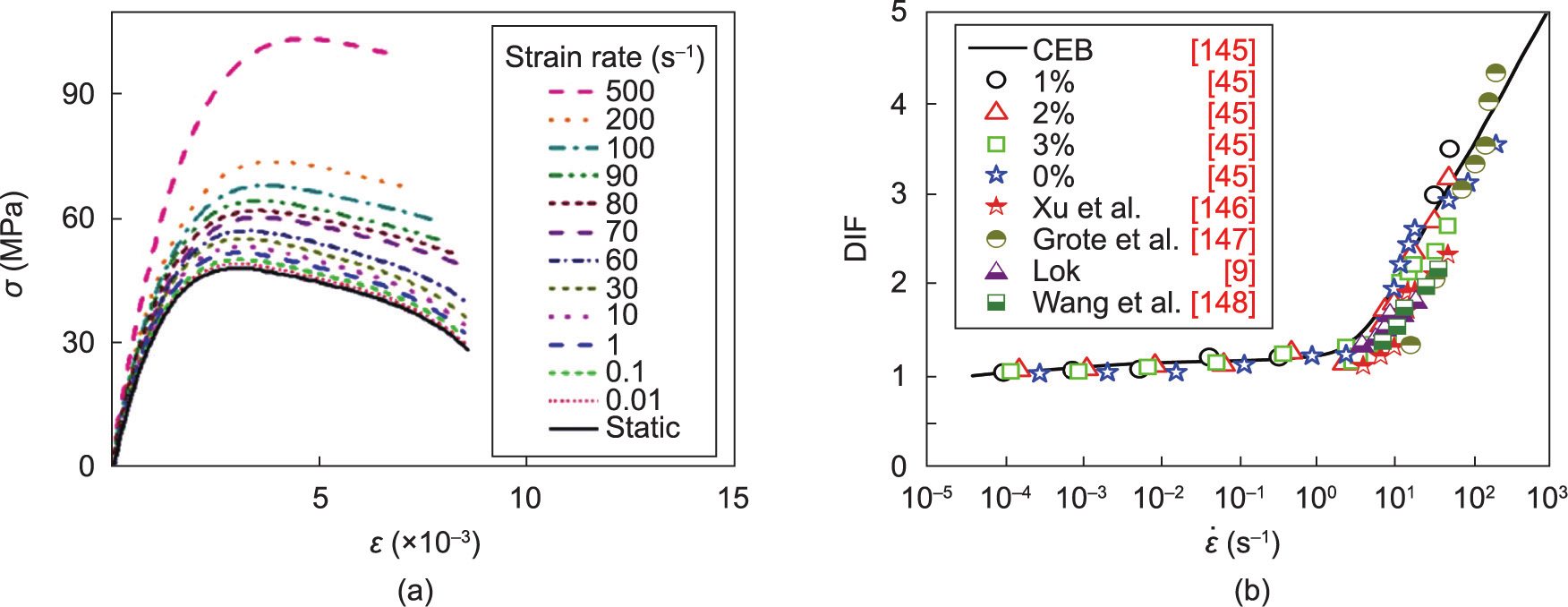
Fig. 17. Uniaxial compressive results of SFRC with steel fibers of 3%. (a) Stress–strain curves (σ: stress; ε: strain). Reproduced from Ref. [45] with permission. (b) DIF (: strain rate) [8,45,144–147].
To investigate the effect of steel fiber on the dynamic compressive properties of SFRC containing coarse aggregates, Xu et al. [20] simulated dynamic impact behaviors of SFRC using the axisymmetric mesoscale model consisting of hook-end fibers, aggregates, and mortar matrix (Fig. 4(a)). The dynamic failure patterns of plain concrete and SFRC under the strain rate of 471 s–1 are shown as the effective plastic distribution in Fig. 18. As can be observed from the mesoscopic results in Fig. 18, compared with the complete brittle failure of plain concrete, the SFRC showed a more excellent ductile performance, and cracking failure only appeared on the specimen edge, which was attributed to the crack-bridging effect of hookend fiber embedded in the mortar matrix [149–151]. Besides, through the comparison of numerical and experimental DIF of SFRC under different strain rates, shown in Fig. 19, it could be learned that the steel fiber insignificantly increased the compressive DIF of SFRC at low strain rate. However, the compressive DIF of SFRC under high strain rate loading was significantly enhanced with the increase of steel fiber dosage, which is because of the SFRC’s capability of absorbing more fracture energy under a high strain rate loading [152].
《Fig. 18》

Fig. 18. Effective plastic strain distribution of SFRC with different contents of steel fibers: (a) plain concrete; (b) 0.6 vol% SFRC; (c) 1.2 vol% SFRC; and (d) 1.8 vol% SFRC. Reproduced from Ref. [20] with permission.
《Fig. 19》
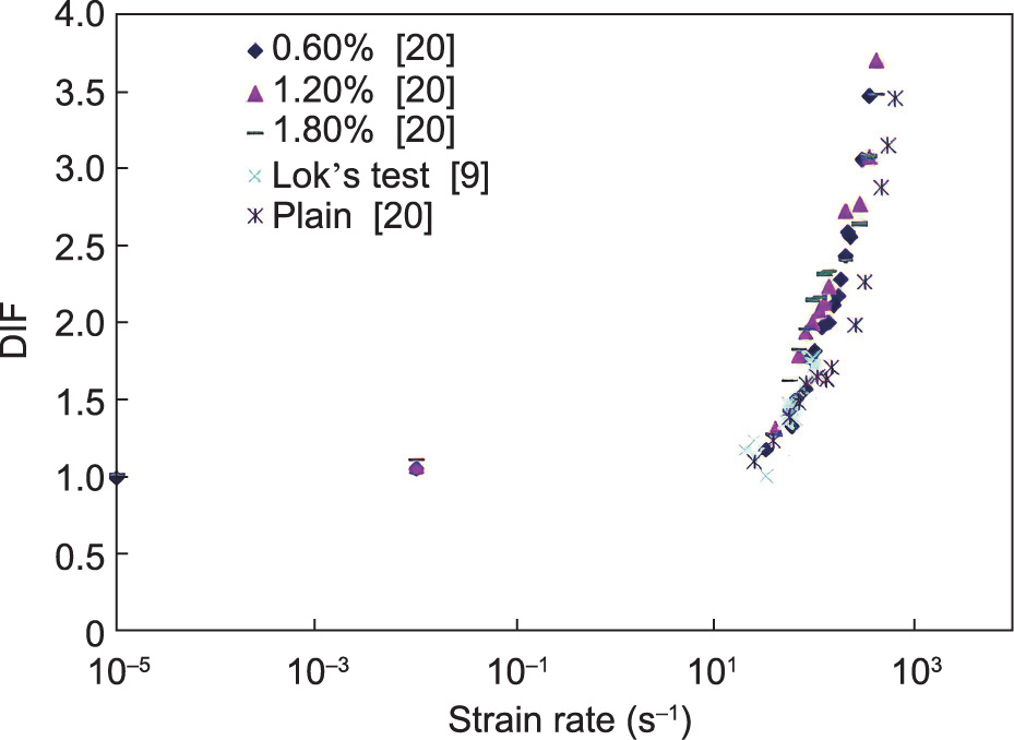
Fig. 19. Comparison of numerical and experimental DIF of SFRC with different contents of steel fibers [9,20].
《4.2. Tensile properties of SFRC》
4.2. Tensile properties of SFRC
As we previously illustrated, the steel fibers randomly distributed in concrete matrix can play a significant role in delaying or preventing cracks propagation in the mortar matrix and ITZ region. It has been acknowledged that the steel fibers can lead to significant enhancement of ductility and tensile strength of the concrete matrix [24,153]. At the same time, to understand the action mechanism of steel fibers in SFRC under tension, scholars have performed a large number of numerical tests on the tensile behaviors of SFRC, and the numerical tensile tests have been conducted in term of the splitting-tensile [46,59,154], drop-weight impact tensile [44], and direct tensile tests [45]. In this section, the existing mesoscopic simulations on the tensile behaviors of SFRC are reviewed and discussed systematically.
Fig. 20 shows the experimental and numerical failure patterns of SFRC subjected to dynamic splitting-tensile loadings. From the damage distribution in cement matrix (Fig. 20(b)) and steel fibers (Fig. 20(c)), it can be clearly seen that the rupture phenomenon happened at the diametral plane along the loading direction, and the compressive damage also occurred on the loading position between specimen and load-bearing strips. In addition, the steel fibers near the diametral plane along the loading direction suffered from tensile stress, which is helpful for controlling the specimen rupture along the loading direction. The numerical failure pattern of SFRC had a good agreement with the experimental results, as shown in Fig. 20(a), which provides calibration for the mesoscale modeling approach in investigating the tensile behaviors of SFRC. Liang and Wu [46] simulated the splitting-tensile behavior of cube SFRC specimen using a similar mesoscale model (Fig. 6(c)) as Wu et al. [59], and they found that the damage initiated at the specimen center and then expanded towards to the loading positions along vertical direction (Fig. 21).
《Fig. 20》
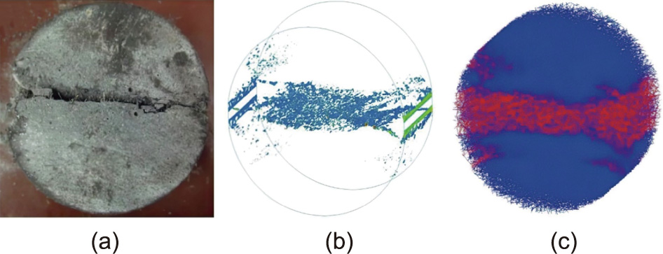
Fig. 20. Comparison of experimental and numerical failure patterns of SFRC under dynamic splitting tension: (a) test results; (b) simulation results for concrete matrix; and (c) simulation results for steel fibers. Reproduced from Ref. [59] with permission.
《Fig. 21》
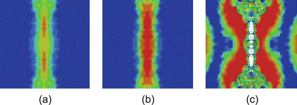
Fig. 21. Damage process along loading axis of the cube SFRC specimen: (a) step 24/100, (b) step 51/100, and (c) failure. Reproduced from Ref. [46] with permission.
Hao et al. [154] employed a 2D three-phase mesoscale model to simulate the SFRC with spiral fibers and aggregates under dynamic splitting tension. Fig. 22 exhibits the dynamic splitting-tensile failure patterns of SFRC with different aggregate shapes (circular and polygon) and fiber contents (1%–3%). As can be seen, the cracking mode of SFRC specimen changed from one major crack in the diametral plane (Figs. 22(a)) to numerous fine cracks (Figs. 22(b) and (c)). Furthermore, there was little difference in the cracking patterns of SFRC specimens with circular and polygon aggregates. Then, they concluded that the aggregate shape had an insignificant effect on the cracking patterns of SFRC, which was attributed to the crack propagation velocity in SFRC under dynamic loading was too fast to allow these cracks to propagate in the weak region, but they could penetrate the coarse aggregates. Thus, the cracking path in concrete would not be affected by the change of aggregate shape [154].
《Fig. 22》

Fig. 22. Dynamic splitting-tensile failure modes of SFRC with different fiber contents. (a) 1.0% SFRC at the strain rate of 3.9 s–1 , (b) 2.0% SFRC at the strain rate of 10.9 s–1 , and (c) 3.0% SFRC at the strain rate of 19.4 s–1 . Reproduced from Ref. [154] with permission.
Utilizing the V-notched SFRC mesoscale model shown in Fig. 4(b), Xu et al. [44] investigated the dynamic tensile behavior of plain concrete and SFRC with hook-end steel fibers, as shown in Fig. 23. As can be seen, cracking failure occurred in the notch and propagated vertically toward the specimen support. The tensile cracks were in the form of one major crack and many bifurcations around it. With the increase of fiber volume fraction, there were more bifurcations occurring in SFRC, implying that more fracture energy was absorbed by steel fibers, which is consistent with Hao et al.’s simulations [154] (Fig. 23).
《Fig. 23》
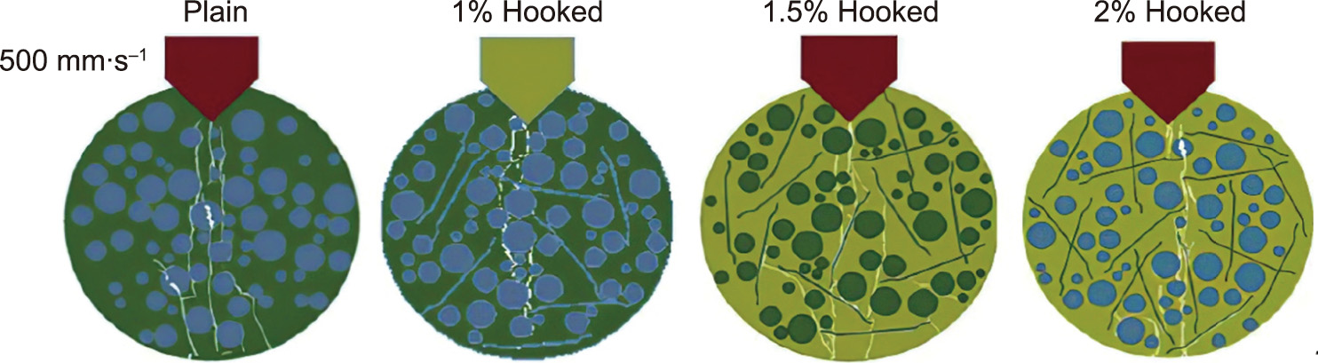
Fig. 23. Failure modes of plain concrete and SFRC with different fiber fractions. Reproduced from Ref. [44] with permission.
In addition to the splitting tensile and rupture simulations, Fang and Zhang [45] conducted a series of numerical split Hopkinson tensile bar (SHTB) tests to investigate the dynamic uniaxial tensile properties of SFRC. Fig. 24(a) presents the static and dynamic tensile stress–strain curves of SFRC with steel fibers of 3% under the strain rate of 0.001–100 s–1 . It can be observed that the tensile peak-stress of SFRC gradually increases with the increase of strain rate. Fig. 24(b) plots the numerical tensile DIF of SFRC with different fiber contents at different strain rates. Compared the numerical DIF values with CEB predictions, it can be found that the former is relatively lower than that of the latter when the strain rate was below the strain rate 30–32 s–1 , while an opposite relationship between them appeared when the strain rate exceeded the critical strain rate. Another one can be found is that the tensile DIF of SFRC showed a notable increase after the strain rate of 32 s–1 , which is the so-called critical strain rate  . Compared with the specified of 30 s–1 by CEB, the of SFRC is relatively higher. Similar to the relation of compressive DIF with fiber content, there is little difference in the tensile DIF of SFRC when the strain rate is below 50 s–1 , while a slight effect of fiber content on the tensile DIF can be observed after 50 s–1 .
《Fig. 24》
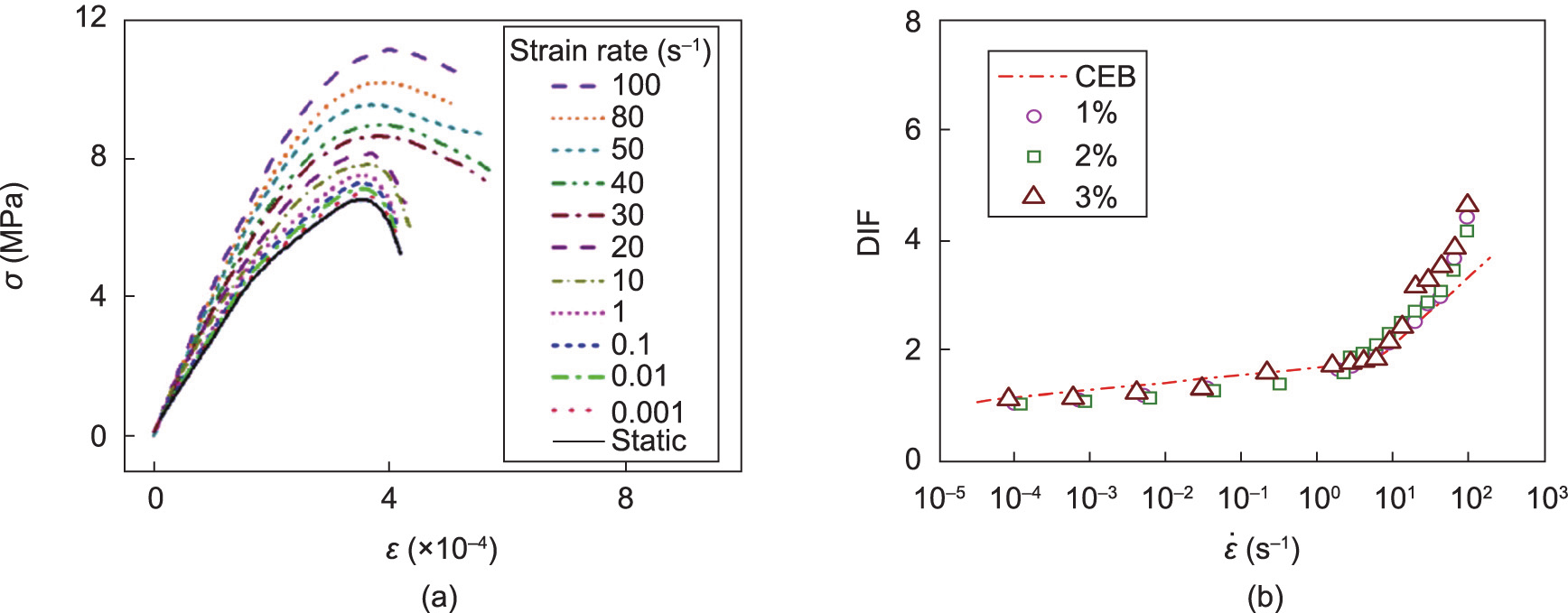
Fig. 24. Uniaxial tensile results of SFRC with steel fibers of 3%: (a) stress–strain curves and (b) DIF. Reproduced from Ref. [45] with permission.
《4.3. Blast behaviors of SFRC》
4.3. Blast behaviors of SFRC
For the purpose of investigating the blast resistance of SFRC under close-in or contact explosions, numerous experiments have been conducted in the past decades. It has been confirmed that the addition of steel fibers in SFRC can improve its ductility [87], loadbearing capability [155], crack inhibition [156], and energy absorption without fragments [157]. To simplify the test procedure and reduce the cost of full-scale test, available blats tests for SFRC members, such as slab, beam, and column, were mainly conducted utilizing the single degree of freedom (SDOF) system to predict the dynamic response of structure members under blast loadings [158,159]. It has been acknowledged that the SDOF system can yield satisfactory overall predictions, but it has limitations in predicting the localized structural response of SFRC member under blast loadings. Therefore, a numerical modeling method with computer simulation that can provide more reliable predictions of structural damage and behavior, and has been extensively used in modeling the concrete structure response to blast loadings. Luccioni et al. [160] employed a homogeneous mesoscale model to simulate the SFRC slab under blast loadings. Through the comparison of experimental and numerical investigations, it was found that the homogeneous model was unable to reproduce the structural behavior of SFRC under blast loads. For instance, the effect of steel fibers added in concrete matrix on the cratering, spalling, and flexural failure of SFRC could not be well simulated using the homogeneous models. Thus, a more detailed mesoscale model with consideration of steel fibers should be developed to simulate and predict the blast behavior of SFRC.
To improve the computational efficiency, Peng et al. [84] established a mesoscale heterogeneous model (similar to that in Fig. 6(c)) and a macroscale homogeneous model to model the SFRC slab, as shown in Fig. 25, where a cube region containing random steel fibers was located in the center of SFRC slab. The finite element method and the smoothed particle hydrodynamics (SPH) method [161] was employed to investigate the SFRC slab and the explosive charge, respectively. The erosion technique was used to simulate the damage failure of SFRC slab, and the erosion criterion for the concrete matrix and SFRC slab was set as the maximum principal strain of 0.2 and 0.3 in (1 in = 2.54 cm) this simulation. As can be seen from Fig. 25, significant localized damage failure occurred at the central part of SFRC slab. Further, in comparison with the experimental results (Fig. 26), it can be seen that the numerical crater results (diameter and depth) were closed well with the test results. This indicates that the developed mesoscale modeling approach is capable of predicting the blast behaviors of the SFRC slab.
《Fig. 25》
Fig. 25. (a) Numerical model and (b) simulation results of the SFRC slab under contact explosions. Reproduced from Ref. [84] with permission.
《Fig. 26》
Fig. 26. Comparison of numerical and test crater characteristics: (a) crater diameter and (b) crater depth. Reproduced from Ref. [84] with permission.
Fang and Zhang [45] numerically investigated contact explosion responses of SFRC with different contents of steel fibers and the 3D mesoscale model of cylinder SFRC specimen and cube explosive charge. The Lagrangian–Eulerian method was adopted to simulate the contact explosion of SFRC, where the air and explosive charge were simulated by the Euler mesh, and SFRC was modeled by the Lagrange mesh. An SFRC model with dimensions of φ7 cm × 3.5 cm was confined by a steel hoop and free at the top/bottom surface, and a cube explosive was placed at the center of top surface of the SFRC model. The effects of fiber content and explosive amount on the failure patterns of SFRC was investigated numerically.
Fig. 27 shows the crater and spallation characteristics of the plain concrete and SFRC. The crater on the top surface was directly formed by the compressive stress wave, while the spallation occurring on the bottom surface was caused by the tensile stress that resulted from the compressive stress wave propagated in the free bottom surface. As can be seen from Fig. 27, the crater and spallation of concrete under contact detonation could be realistically simulated using the 3D mesoscale model. Moreover, it can be observed that the size of crater and spallation of concrete in simulations were in a good agreement with the experimental results, which gives a calibration for the 3D mesoscale modeling approach. They also investigated the effect of steel fiber content on the blast responses of SFRC by evaluating the diameter and depth variation of crater and spallation. It was found that both the diameter and size of crater and spallation of plain concrete were larger than the SFRC. It was also found that the size of crater or spallation of SFRC was associated with the fiber content, which is mainly attributed to the fiber bridge effect that confined the cracking of concrete at post-failure stage and improved the energy absorption capability. Besides, both the diameter and depth of crater/spallation of SFRC showed a linear increasing tend with the amount of explosive.
《Fig. 27》
Fig. 27. Comparison of numerical and experimental damage of SFRC. (a) Crater characteristic of SFRC and (b) spallation characteristic of SFRC. Reproduced from Ref. [45] with permission.
《Fig. 28》
Fig. 28. Effective plastic strain of concrete matrix and fibers of SFRC. Reproduced from Ref. [45] with permission.
To gain a better understanding for the action mechanism of steel fibers in SFRC under contact explosions, Fang and Zhang [45] explicitly modeled the blast responses of concrete matrix and steel fibers shown in Fig. 28. Compared with the distribution of effective plastic strain in plain concrete, the strain distribution of concrete matrix in SFRC was uneven and showed few changes with the increase in the explosive amount. Moreover, for a given fiber content and explosive amount, it was noted that the effective plastic strain of steel fibers was relatively higher than that of the concrete matrix, which is because the fibers played a significant role on the enhancement of concrete toughness under contact detonation. The strain difference between the steel fibers and concrete matrix tended to more significant with the increase of Vf, implying that the steel fibers in SFRC with high Vf played a bigger role in improving the explosion resistance of SFRC. In summary, the steel fibers included in concrete matrix can exhibit prominent role in the improvement of the explosion resistance for SFRC, and the SFRC with higher Vf (3%) tends to show a superior ductile performance than that of those with low Vf (0%–2%).
《5. Conclusions》
5. Conclusions
This work comprehensively reviewed the state-of-the-art mesoscopic models and simulations for SFRC under dynamic loadings, that is, uniaxial compression, splitting and direct tension, and blast loadings. Based on literature reviews, some significant conclusions were drawn from the above review and discussions:
(1) There are two methods for representing of the mesostructure of FRC: The first method is the image-processing method by means of XCT, which enables us to generate a reliable mesostructure model of FRC. An alternative method is to establish some random line or solid elements to represent the fiber models in concrete, through which the 2D and 3D mesoscale models could be developed. Generally, the mesoscale model obtained from the second method is precise enough to simulate and investigate the mechanical response of SFRC under static and dynamic loadings, and it is rather economical in modeling and calculating than the XCT image-based method.
(2) Depending on the coarse aggregate models included in mesoscale model, two types of mesoscale models were developed and employed for the mesoscale modeling of SFRC materials. Considering the computational cost, the two-phase mesoscale model consisting of steel fiber and mortar matrix is suitable for the mesoscale modeling of SFRC under different loading conditions.
(3) According to the available test and numerical applications, it was indicated that the dynamic behaviors of SFRC are significantly affected by the fiber configurations, that is, the shape, length, and content. Thus, different types of fibers such as the straight, spiral and hooked fibers, should be established in the SFRC mesoscale model for further simulation of its mechanical responses under dynamic loadings.
(4) Some investigators attempted to added coarse aggregates with different shapes and dimensions, that is, the circular (2D), polygon (2D), sphere (3D) and irregular polyhedron (3D), in the SFRC mesoscale model. From Hao et al.’s simulations [154], it was concluded that the 2D aggregate shape has insignificant influence on the post-cracking behavior of SFRC at low and high strain rates. However, owing to few reports on the simulation results of 3D SFRC model incorporating 3D fibers and random-shaped aggregates, it is still worth exploring the effect of aggregate shape on the dynamic behaviors of SFRC model, which is of certain guidance for the development of future SFRC mesoscale models.
(5) To provide a rational mechanical response description, many different material models have been employed for steel fiber, coarse aggregate, mortar matrix and ITZ between these three phases. However, it can be noted from the existing mesoscopic simulations that most investigators assumed aggregates and mortar matrix to be linearly elastic materials and neglected the plastic behaviors of them under dynamic loadings. Furthermore, the elastic–plastic material model concerning the strain rate effect and material plasticity of aggregates, namely the HJC model, modified Rucker–Prager/cap plasticity model, continuous surface cap model, and K&C model, should be employed in the SFRC models.
(6) It can be found from existing research that the interfacial relationship between fiber/aggregate and concrete matrix is closely associated with the simulation results. In particular, the fiber–matrix interfacial relationship is the foundation to analyze the mechanical properties of SFRC, which is associated with many influencing factors, that is, the fiber shape, inclination angle, surface treatment, embedded length, pull rate, fiber modulus, and matrix property. There are two types of methods developed and employed to model the bonding relationship between fiber and concrete matrix, that is, the explicit simulation of ITZ as an annular region around fiber or the implicit contact algorithm describing the interfacial relationship between fiber and concrete matrix. Due to the limitation of increased difficulties in finite element meshing and computational efforts, the ITZ method is less practical than the contact algorithm method. Generally, three different contact algorithms such as the same node assumption, 1D contact algorithm, and coupling algorithm, have been employed to describe of bonding relationship between the fiber and matrix, which should be based on the fiber pullout behavior in different types of matrix environment.
(7) The findings of the example applications of SFRC under dynamic and impact loads indicate that the abovementioned mesoscale models have advantages in simulating and predicting the mechanical behaviors of the SFRC material and member, that is, the stress–strain relation, stress distribution, post-cracking failure, cater, and spallation. However, it should be noted that more detailed and efficient modeling approaches need to be developed to simulate the SFRC material and structural members under extreme loadings, such as 3D mesoscale model with irregular aggregates and random steel fibers. Besides, the bond–slip behaviors and failure modes of steel fibers having different modulus should be well considered during the modeling process, which is significantly associated with the energy absorption capability (or toughness) of SFRC under impact loadings. Furthermore, the mesoscale modeling approach can be also used in the premodeling procedure to give further guidance for the prediction and design of SFRC material and structure. In summary, the mesoscopic modeling approach has enormous potential in the future investigation, development and application of SFRC.
《Acknowledgments》
Acknowledgments
The authors gratefully acknowledge the financial support from the National Natural Science Foundation of China (52178190 and 52078250), the Science and Technology on Near-Surface Detection Laboratory (6142414200505), and the Interdisciplinary Innovation Fundation for Graduates, Nanjing University of Aeronautics and Astronautics (KXKCXJJ202005). The support provided by the China Scholarship Council (202006830096) during a visit of Zhangyu Wu to University College London is also sincerely acknowledged.
《Compliance with ethics guidelines》
Compliance with ethics guidelines
Jinhua Zhang, Zhangyu Wu, Hongfa Yu, Haiyan Ma, and Bo Da declare that they have no conflict of interest or financial conflicts to disclose.


 京公网安备 11010502051620号


