
When an electric current passes through an electrical conductor, it generates heat by converting electrical energy into thermal energy. The conversion was discovered to follow Joule’s law in 1841. Since then, electrical heating has been widely used in many aspects of our daily lives and industries, and it has been taken for granted for centuries [1–5]. However, it must be noted that both free electrons and ions are current carriers; therefore, there are both electronic conductors and ionic conductors [6–11]. Interestingly, Joule heating is entirely based on electronic conductors, and minimal attention has been paid to the potential of ionic conductors for heating purposes. This is because of electrolysis, although various ionic conductors (electrolytes) have been explored for electrochemical reactions that generate useful chemical products, unwanted electrochemical reactions can cause damage, such as corrosion, fouling, and contamination [12–15]. Furthermore, many electrochemical applications for chemical production are limited to direct current (DC) and low voltage (typically < 5 V) conditions to avoid the decomposition of ionic conductors [16–21]. It remains considerably challenging to develop practical Joule heating with ionic conductors that is free of electrochemical reactions.
Broadly, there are numerous types of ionic conductors in both liquid and solid forms, including various types of water (pure water, tap water, river water, sea water, and wastewater), ionic liquids, salts, and polyelectrolytes, as well as biological ionic systems (nerves, muscles, tissues, and body fluids). In an ionic conductor, transportable ions serve as current carriers. The heating effect can be observed for all the above ionic conductors and is known as ohmic or Joule heating. However, the heating process is inevitably accompanied by electrochemical reactions. In 2006, Bansal and Chen [22] compared the heating of milk with a power supply at two frequencies (10 kHz vs 50 Hz) and found a significant reduction in electrode corrosion and fouling for the lower frequency. While this phenomenon has been observed, the mechanism for the optimized frequency has not yet been elucidated.
Electrochemical reactions occur at the electrode/electrolyte interface. Ions accumulate and concentrate to form an electric double-layer capacitor (EDLC), which can break down (electron transfer) given adequate time [23–26]. It is clear that the key to suppressing electrochemical reactions is to minimize the ion concentration at the interfaces. This analysis inspired us to explore the potential of heating with an alternating current (AC) in an optimized frequency range.
We propose heating ionic conductors with a zero-phase frequency, which is the frequency at which the phase angle of the heating system is close to zero. At this frequency, the ionically conductive system behaves as a pure resistor [5,11,23]; ions have insufficient time to form an EDLC, blocking electron transfer and thus inhibiting electrochemical reactions. At the zero-phase frequency, an ultrahigh voltage (> 100 V) can be applied to ionic conductors, yielding a high heating power; power at the kilowatt level was tested without any apparent electrochemical reactions. Ionic Joule heating is simple, direct, fast, and highly efficient for energy conversion. Both liquid and solid electrolytes, including saline solutions, tap water (even pure water), milk, ionic liquids, hydrogels, ionogels, and ionic conducting ceramics, are demonstrated in this work.
Fig. 1(a) illustrates the ionic Joule heating mechanism at a zerophase frequency, and Fig. 1(b) compares it to other current heating methods based on the AC frequency range. At a low frequency (Fig. 1(a), left), the electrolyte is heated, but ions migrate and accumulate at the electrode–electrolyte interface to form an EDLC, resulting in severe electrochemical reactions. At the zero-phase frequency (Fig. 1(a), middle), the electrolyte is heated with minimal electrochemical reactions. Because the electric field switches very fast, ions travel back and forth over a short distance and have insufficient time to reach the electrodes to form an EDLC, thus suppressing electrochemical reactions. However, at an ultrahigh frequency (Fig. 1(a), right), the movement of ions cannot match the switching of the electric field. Consequently, dipoles start to polarize and store the electrical energy, which restricts the conversion to heat.
《Fig. 1》

Fig. 1. Schematic of ionic Joule heating. (a) Illustration of the ionic Joule heating mechanism. (b) Comparison of ionic Joule heating to other current heating methods based on the AC frequency range. f: frequency; V: voltage; t: time.
We studied the impedance properties of saline solutions with various concentrations in a U-type tube with 304 steel electrodes. As shown in Figs. 2(a) and (b), the impedance modulus (|Z|) and phase angle (–Φ), respectively, greatly depended on the test frequency. In the low-frequency range (from 10 Hz to 1 kHz), |Z| decreased sharply by over an order of magnitude with increasing frequency, and –Φ decreased from over 60° to nearly 0° because of the influence of the EDLC at the electrode–electrolyte interface. As the frequency increased to the zero-phase region (approximately from 10 kHz to 1 MHz), the electric field began switching very fast. The ions in the electrolyte travelled only a short distance and had insufficient time to migrate to the electrode–electrolyte interface to form an EDLC; that is, the ions experienced resistance to movement. Thus, the zero-phase frequency is optimal for heating the electrolyte.
We also tested the voltage–current behavior of a 1 mol·L–1 NaCl solution in a U-type tube at 100 kHz. The data in Fig. 2(c) show a highly linear correlation between the resulting current and applied voltage (R2 = 0.9999), demonstrating that the saline solution behaved as a pure resistor at the zero-phase frequency. The voltages far exceeded the theoretical decomposition onset (1.23 V) of water. Thus, high-power heating of ionic conductors without electrochemical reactions was achieved. The Joule heating behaviors of the 1 mol·L–1 NaCl solution were compared at different frequencies and 110 V. The solutions were heated to their boiling points, and Figs. 2(d) and (e) show photographs of the resulting heating tubes. At 60 Hz, severe electrochemical reactions clearly occurred. The electrode was visibly corroded, and the solution was seriously polluted. In contrast, at the zero-phase frequency (100 kHz), both the solution (Fig. 2(d)) and electrodes (Fig. 2(e)) were clean, indicating that no electrochemical reactions occurred. This conclusion was verified by scanning electron microscopy (SEM) images of the 304 steel electrodes after heating (Fig. 2(f)). The electrode operated at 100 kHz was clean, while the one at 60 Hz was dirty.
《Fig. 2》
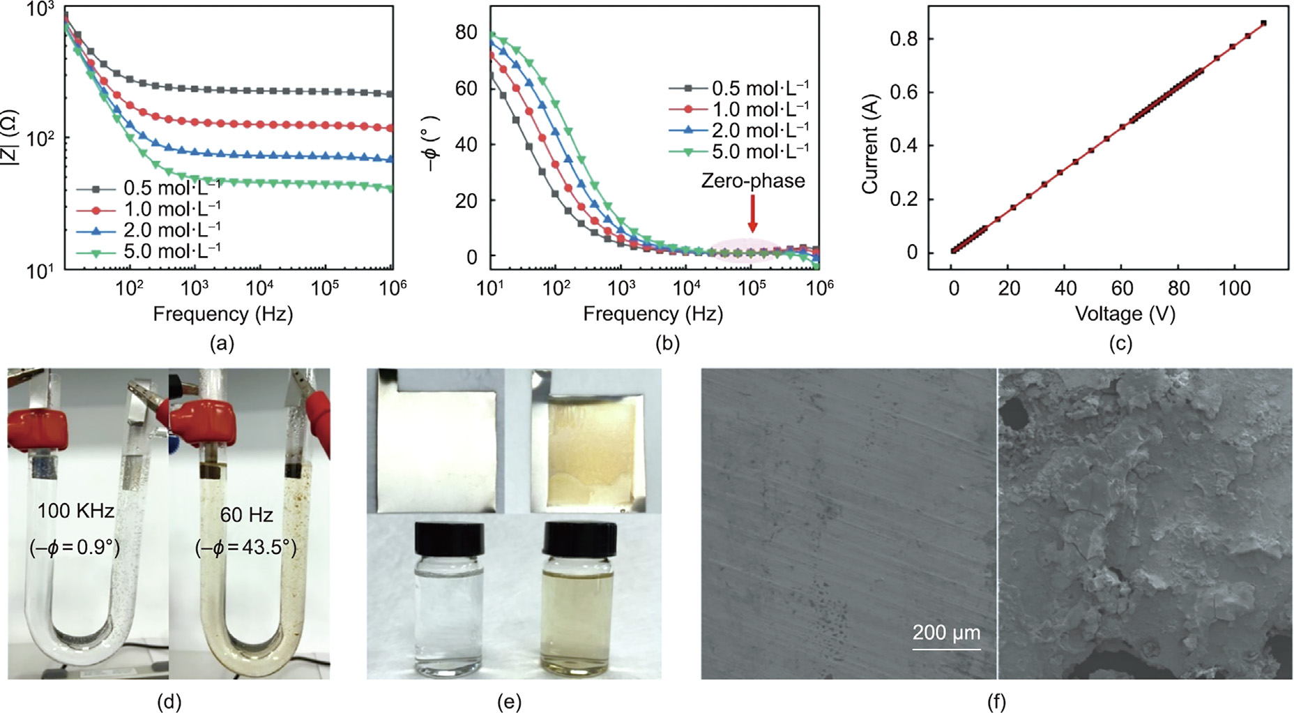
Fig. 2. Demonstration of the ionic Joule heating method. (a) Impedance modulus and (b) phase angle spectra of NaCl aqueous solutions with various concentrations. (c) Applied voltage versus current of the 1 mol·L–1 NaCl solution at a zero-phase frequency (100 kHz). (d, e) Photographs of the resulting heating tube and electrodes. (f) SEM images of the electrodes after Joule heating at 100 kHz (left) and 60 Hz (right).
The zero-phase frequency is not universal for all ionic conductors. Many factors can affect the impedance spectra, such as the types of electrodes and electrolyte, ion concentration, shape of the heating device, and temperature. It must be noted that regardless of changes in the above factors, a frequency with a phase angle near zero is a prerequisite for Joule heating of ionic conductors. It is only at a zero-phase frequency that the electrochemical reactions can be greatly suppressed. Different heating systems have different zero-phase frequencies that must be screened in advance (see Figs. S1 and S2 in Appendix A).
Fig. 3 shows the design and demonstration of ionic Joule heating for several liquid electrolytes. Fig. 3(a) is a schematic of a rectangular heating device with a 10–2 mol·L–1 NaCl heating solution and 304 steel electrodes. The parallel electrodes help to generate a uniform electric field. It is evident from the infrared images in Fig. 3(b) that the heating was uniform without a noticeable temperature gradient. The impedance spectrum showed that the zero-phase of 10–2 mol·L–1 NaCl was near 10 kHz, which was subsequently applied to heat the solution. The heating rate was varied by changing the applied voltage (Fig. 3(a)). A high voltage resulted in a high initial power, the heating curves were smooth, and the heating process was easily controlled. Fig. 3(d) shows the heating current curves. The current increased as time progressed, indicating an increasing heating power. This is because as the temperature increases, the ions in the solution can move more freely, resulting in an increased ionic conductivity and a decreased resistance. This tendency is opposite to that of electronic conductors, in which the resistance increases and conductivity decreases with increasing temperature. At a fixed voltage, the resistance decreases as the temperature increases with time. Thus, the current increases with increasing time. The heating uniformity of the ionic liquid is also demonstrated in Fig. S3 in Appendix A.
《Fig. 3》

Fig. 3. Ionic Joule heating of liquid electrolytes. (a) Schematic of a heating device with a 10–2 mol·L–1 NaCl heating solution. (b) Infrared images of the heating solution. (c) Heating curves at various applied voltages. (d) Current versus time at various applied voltages. (e) Schematic (upper) and infrared image (lower) of a designed wipe-type heating device. (f) Heating curves of a flowing 1 mol·L–1 NaCl solution (307 mL·min–1 ) at a zero-phase frequency. (g) Schematic of a heating device designed for liquids with a low ionic conductivity. (h) Heating curves of flowing tap water (150 μS·cm–1 ) at a zero-phase frequency. (i) Photograph of a designed 200 mL milk heating device. (j) Temperature and current versus time of the milk. (k) Schematic of a chemical vessel with steel annuli serving as the electrodes and water as the medium. (l) Heating curves of a designed ionic Joule heating device and traditional jacket-circulating water heating device.
Fig. 3(e) presents a schematic (upper) of a designed wipe-type heating device, which was used to heat flowing liquid electrolytes. In the demonstration, a 1 mol·L–1 NaCl solution with a flow rate of 307 mL·min–1 was heated. By simply applying a voltage through the steel wipe electrodes, the flowing solution was directly heated, as evident from the infrared image of the heating device. Fig. 3(f) shows the heating curves of the output solution. Upon voltage application, the temperature of the output solution increased to its equilibrium temperature in seconds, and the equilibrium temperature could be controlled by varying the applied voltage. This design has proven to be a powerful tool for flow chemistry and engineering [27–29]. A temperature-sensitive color-change flowing system is demonstrated in Fig. S4 and Movie S1 in Appendix A.
For solutions with low ionic conductivity, we designed another flowing Joule heating device to decrease the driving voltage (P = U2 ·R–1 ). As shown in Figs. 3(g) and (h) and Appendix A Fig. S5, tap water (10–4 –10–5 S·cm–1 ) and even pure water (10–6 –10–7 S·cm–1 ) were successfully heated using this design, suggesting that Joule heating can be achieved with a trace amount of ions. The experiment reveals potential applications in kitchens, showering, washing, and hot drinking water. Figs. 3(i) and (j) demonstrate the heating of pure milk, which contains charged proteins and inorganic salts that are also ionically conductive and provide impedance properties similar to those of saline solutions. Heating in this system was also plausible, showing potential applications in food engineering and even direct heating of some biosystems. Further developments in medical applications, such as surgical operations, could also be anticipated where precision heating is desired.
Heating is an important unit operation widely used in chemical industries for both reaction and separation purposes. It is often achieved through jacket heating, which is indirect, nonuniform, time-consuming, and accompanied by the loss of heat via transfer. A simple Joule heating chemical vessel was designed in this study, which is shown in Fig. 3(k). With steel annuli serving as the electrodes, the current passed through the liquid medium (water as a model) and directly generated heat. Fig. 3(l) shows the heating curves of the designed ionic Joule heating system versus a traditional jacket-circulating water heating system. Water in a 1 L vessel was heated from 25 to 80 °C in 6 min by applying an initial power of ~500 W. The heating time was shortened by four to five times compared to that of jacket heating. The advantages of ionic Joule heating over traditional jacket-circulating heating would be more profound in larger-volume heating applications. It must also be noted that, in theory, ionic Joule heating achieves complete conversion from electrical energy to thermal energy. A small energy loss could be caused by the volatilization of water from open containers and vessels to the environment. Based on the energy balance, we calculated the energy conversion efficiency to be approximately 94% in the U-tube heating experiments with the NaCl solution.
Heating is also fundamental in material processing, which often involves heating solids. In addition to the above liquid electrolytes, we also demonstrated ionic Joule heating of solid-state ionic conductors. Fig. 4(a) shows infrared images of a heated agar hydrogel. The gel generated heat directly, and the heating was uniform. Because heat convection in the gel is restricted, it is challenging to realize uniform heating by conventional heating methods (Movie S2 in Appendix A). Therefore, the ionic Joule heating developed in this work has a clear advantage over existing heating methods. Fig. 4(b) shows the heating of an ionic conductive ceramic, Li1.5Al0.5Ge1.5(PO4)3 (LAGP). Again, heating was quick, uniform, and well controlled, showing great potential for ceramic and salt processing.
《Fig. 4》
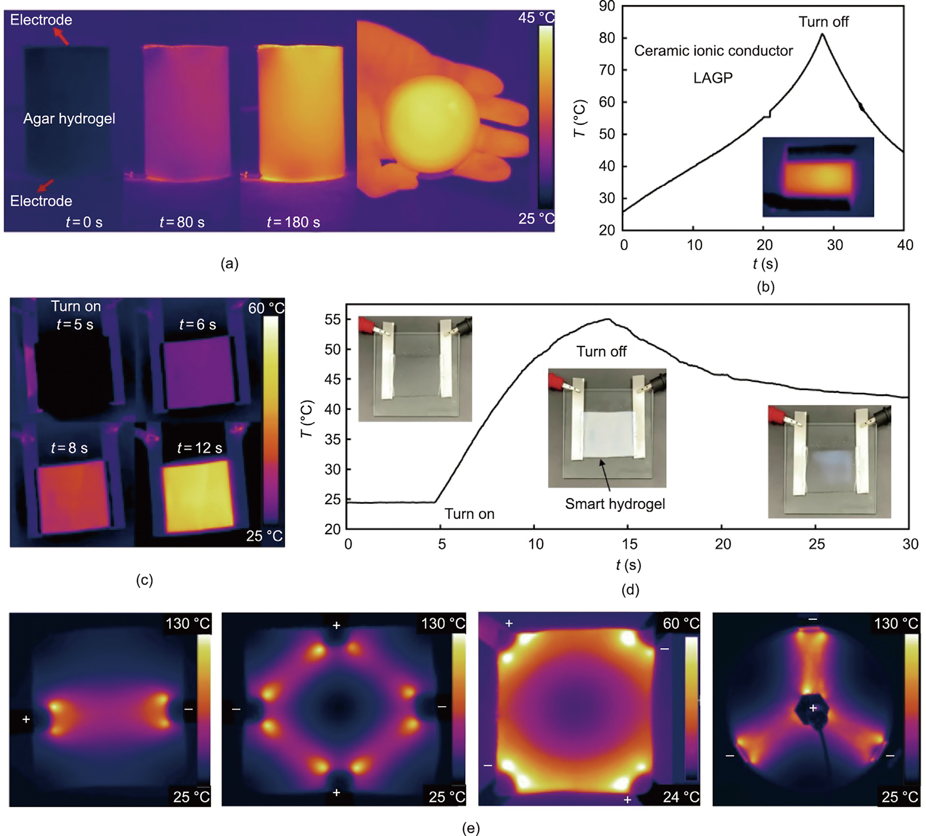
Fig. 4. Ionic Joule heating of solid-state electrolytes. (a) Ionic Joule heating of a cylindrical agar hydrogel; the infrared images indicate that the gel generated heat directly, and the heating was uniform. (b) Heating curve of a ceramic ionic conductor Li1.5Al0.5Ge1.5(PO4)3 (LAGP); inset is an infrared image during the heating process. (c) Ionic Joule heating of a smart hydrogel membrane. (d) Heating curve of the smart hydrogel; the hydrogel became opaque when the temperature exceeded its LCST. (e) Patterned infrared images of ionogel membranes during ionic Joule heating with different electrode configurations.
The recent advent of thermally responsive polymers provides a good opportunity to develop smart materials with on–off switching properties, such as shape, color, strength, conductivity, and solubility. However, precise heating remains challenging. Figs. 4(c) and (d) show the switching of a smart hydrogel membrane, assisted by powerful ionic Joule heating. Based on the infrared images (Fig. 4(c)), the temperature distribution was clearly uniform during the heating process. The hydrogel became opaque (Fig. 4(d)) when the temperature exceeded its lower critical solution temperature (LCST) (Movie S3 in Appendix A). In addition, by configuring the electric field lines, we obtained patterned heating or precise local heating. Fig. 4(e) shows the patterned infrared images obtained during ionic Joule heating of ionogel membranes with different electrode configurations (Movie S4 in Appendix A). Heat was generated from the movement of ions, which resulted from the external electric field. Therefore, the infrared image of heating exhibited the same configuration as that of the electric field.
A final point is that there is a fundamental difference between this work and the work published in Nature Nanotechnology 2017. These two works are not in the same field. Dudchenko et al. [5] used a carbon nanotube (CNT) membrane as a heating device to heat salty water, which is traditional Joule heating using an electronic conductor (CNT membrane) to generate heat and then transfer the heat to salty water. The present work focused on ionic Joule heating, in which electric current directly passes through salty water to generate heat. In this method, the ions in the water serve as heat generators, and the electron heat generators are eliminated.
In conclusion, by applying a zero-phase frequency, ultrahigh voltages (> 100 V) were used to heat ionic conductors free of noticeable electrochemical reactions, and heating powers at the kilowatt level were obtained. Joule heating of both liquid and solid electrolytes was demonstrated, including saline solutions, tap water (even pure water), milk, ionic liquids, hydrogels, ionogels, and ionically conductive ceramics. The method of ionic Joule heating is simple, direct, fast, uniform, and clean, without energy loss during conversion from electricity to heat. It shows great potential in a wide range of applications, such as food processing, domestic water heating, chemical reactions and separation, ceramic processing, salt making, and even medical operations and surgeries where precise heating is required.
《Acknowledgments》
Acknowledgments
This work was supported by the Program for the Guangdong Introducing Innovative and Entrepreneurial Teams (2017ZT07C291); Shenzhen Science and Technology Program (KQTD20170810141424366); National Natural Science Foundation of China (22078276 and 22005260); 2019 Special Program for Central Government Guiding Local Science and Technology Development: Environmental Purification Functional Materials Research Platform, Shenzhen Key Laboratory of Advanced Materials Product Engineering (ZDSYS20190911164401990); and China Postdoctoral Science Foundation (2019TQ0307).
《Authors’ contributions》
Authors’ contributions
Lei Shi conceived the idea and designed the research. Lei Shi, Zongyi Han, and Yixuan Feng performed the experiments. Lei Shi, Changgeng Zhang, Qi Zhang, and He Zhu analyzed and interpreted the results. Lei Shi and Shiping Zhu drafted the manuscript, and Shiping Zhu supervised the project, and all authors contributed to the writing of the manuscript.
《Compliance with ethics guidelines》
Compliance with ethics guidelines
Lei Shi, Zongyi Han, Yixuan Feng, Changgeng Zhang, Qi Zhang, He Zhu, and Shiping Zhu declare that they have no conflict of interest or financial conflicts to disclose.
《Appendix A. Supplementary data》
Appendix A. Supplementary data
Supplementary data to this article can be found online at https://doi.org/10.1016/j.eng.2022.03.004.


 京公网安备 11010502051620号


