

《1. Introduction》
1. Introduction
To promote the adjustment of the energy structure, the Carbon Peak and Carbon Neutrality Strategy was proposed in September 2020 in China [1–8], with a commitment to drastically reduce China’s carbon emissions. The large-scale development and efficient utilization of renewable energy has become an effective means to decrease carbon emissions. In March 2021, President Xi Jinping proposed building a future renewable-energy-dominated power system, which has accelerated the development of renewable energy generation [9]. China’s onshore wind and solar energy resources are mainly located in the north, northwest, and northeast regions, while the load centers are mainly in the central and eastern regions. Due to the reverse distribution of resources and load, bulk power long-distance transmission is necessary. Compared with high-voltage alternating current (HVAC), high-voltage direct current (HVDC) is superior in terms of transmission capacity and distance. Therefore, line-commutated converter (LCC)-based HVDC (LCC-HVDC) transmission over long distances is the dominant form of large-scale utilization of onshore renewable energy in China.
By the end of 2020, a total of 23 LCC-HVDC projects had been put into operation or were under construction in China [10,11]. Eight projects transmitting renewable energy with a transmission capacity exceeding 70 GW are listed in Table 1. In the following years, more LCC-HVDC transmission projects will be put into operation, along with the continuous construction of large-scale renewable energy plants with a capacity of about 100 GW in the gobi area.
《Table 1》
Table 1 LCC-HVDC projects for renewable energy transmission across China.

China’s offshore wind power development has been dramatically accelerated [12,13]. Due to its capability for establishing voltage for island systems, voltage source converter (VSC)-based HVDC (VSC-HVDC) transmission is a more advantageous form of utilizing offshore wind power than alternating current (AC) transmission. Modular multilevel converter (MMC)-based HVDC (MMC-HVDC) is the most common form of VSC-HVDC. Recently, several VSCHVDC demonstration projects have been constructed [14,15], and more projects will be constructed for large-scale offshore wind power transmission [16,17]. The planned total installed capacity exceeds 124 GW.
However, the power electronic devices that are extensively used in renewable energy generation and HVDC transmission systems greatly impact grid stability [18]. With the development and utilization of large-scale renewable energy, high-penetration power electronic systems (HPPESs) have gradually formed at the sending end of HVDC transmission [19–21]. Compared with synchronous generators (SGs), power electronic devices have distinct characteristics dictated by the nature of power semiconductors and their control. The operation of power systems has been profoundly changed [22–25] and therefore presents new stability issues and operational challenges. Since 2011, oscillation incidents encountered in Hami (Xinjiang Uygur Autonomous Region, hereinafter referred to as Xinjiang), Guyuan (Hebei Province), and Tongyu (Jilin Province) have resulted in the large-scale tripping off of wind turbines (WTs) [26]. Since 2017, transient over-voltage incidents have been encountered in Jiuquan (Gansu Province), Xilin Gol League (Inner Mongolia Autonomous Region, hereinafter referred to as Inner Mongolia), and Hainan Tibetan autonomous prefecture (Qinghai Province) [27–29]. Over-voltage risks restrict the transmission capacity of renewable energy, and stability issues bring significant technical challenges to the safety and security of HPPESs and the effective utilization of renewable energy.
To address the stability issues of HPPESs, numerous studies have been carried out aimed at the challenges of broadband oscillation. In recent years, stability analysis methods based on impedance modeling have received extensive attention due to their effectiveness in analyzing oscillations between power electronic devices and AC power grids. More specifically, Refs. [30–34] accomplish impedance modeling for grid-connected voltagesource-converters, renewable energy units, LCCs, and VSCs, respectively. Ref. [35] proposes a method for measuring impedance and extracting the characteristics of power electronic devices. Refs. [36,37] implement stability analysis by treating the gridconnected system of power electronic devices as an equivalent two-port network. To suppress oscillation, Refs. [38,39] offer impedance-reshaping strategies by adding active damping or virtual impedance. The existing research achievements are mainly suitable for the stability analysis of grid-connected systems with a single power electronic device. However, when confronted with large-scale renewable energy bases composed of various product types and multiple stations, current methods are insufficient for stability analysis, especially considering the interactions among renewable energy plants, weak AC grids, and HVDC.
Analysis of transient stability issues for HPPESs has also been conducted. In Europe, renewable energy is mainly transmitted by VSC-HVDC. The fault-handling technologies of both renewable energy converters and VSC-HVDC are relatively mature and can achieve fault ride-through by current control optimization [40– 45] based on fully controlled power electronic devices. In comparison, large-scale renewable energy in China is mainly transmitted by LCC-HVDC. During the transient process under grid faults, LCC commutation failure can be prevented by modifying the control strategies of LCCs [46,47] or adopting auxiliary hardware devices [48]. However, the transient over-voltage of renewable energy units at the fault-clearing time is neglected. In addition, the impacts of weak grids and HVDC on the transient characteristics of renewable energy units require further study.
In regard to simulation methods for HPPESs, digital simulation technology based on HYPERSIM for large AC power grids has developed rapidly and is relatively mature [49,50], while the accurate electromagnetic transient (EMT) simulation of LCC-HVDC and VSC-HVDC has been realized with the employment of the converter’s control and protection device [51,52]. In addition, the EMT simulation of a single renewable energy unit employs control hardware-in-the-loop (CHIL) technology, in which dramatic progress has been made [53–55]. However, for the EMT simulation of large-scale renewable energy transmission by HVDC, technical gaps remain in verifying renewable energy model precision and the equivalence of renewable energy plants composed of large quantities of various units in HPPESs.
Based on the stability issues presented by HPPESs, this paper first identifies the technical challenges of HPPESs in Section 2. Then, Section 3 reveals the mechanism of broadband oscillation and transient over-voltage. Section 4 proposes analytical methods for HPPESs, including small-signal analysis and EMT simulation. Several project practices of renewable energy transmissions through HVDC verify the theoretical research in Section 5. Finally, Section 6 concludes the research results and offers suggestions for the construction and operation of the future renewable-energydominated power system.
《2. Technical challenges》
2. Technical challenges
Thousands of renewable energy units are integrated into LCCHVDC through a complex collection network, consisting of three or four step-up transformers in series and long lines. Due to the decreasing number of coal-fired generating units providing commutation voltage and the increasing equivalent impedance introduced by the collection network, the short-circuit ratio (SCR) that is characterized as system strength can be even lower than 1.5 at the interconnection point of renewable energy units. Compared with LCC-HVDC, VSC-HVDC can transmit renewable energy without an AC system, as it can independently establish voltage for island systems. Accordingly, HPPESs have gradually formed at the sending end in the aforementioned applications, whose characteristics are mainly dominated by power electronic devices—that is, photovoltaic (PV) inverters, WT converters, LCCs, and VSCs. Compared with the traditional power system dominated by SGs, the steady-state and transient characteristics of HPPESs are undergoing profound changes, resulting in the following two new types of stability issue:
(1) Broadband oscillation. The control bandwidth of an SG is relatively low (prime mover control: ≤ 0.1 Hz; excitation control: ≤ 2 Hz). The dynamics of power electronic devices in HPPESs mainly depend on the multi-loop control characteristics. Due to the high switching frequency of the semiconductors, the bandwidth of control loops is much larger; for example, the power control loop covers several Hertz, and the current control loop covers hundreds of Hertz. Compared with the low or sub-synchronous frequency oscillation of traditional power systems, supersynchronous or even high-frequency oscillations are introduced into HPPESs, leading to broadband steady-state stability issues.
(2) Transient over-voltage: Under grid fault conditions, the EMT response characteristics of a traditional power system depend on the instantaneous armature response of the SG. In contrast, the transient response characteristics of power electronic devices depend on the multi-loop control and switching of control modes. At the fault-clearing time, instantaneous response deviation caused by control and switching delay can induce transient overvoltage. Because of their weak capabilities of over-voltage and over-current compared with those of SGs, renewable energy converters are prone to trip off under transient over-voltage.
As the abovementioned stability issues in HPPESs present new characteristics, the analysis methods and design principles used for traditional power systems are no longer applicable. The reasons for this are as follows:
(1) Inapplicability of research methods. Traditional steadystate stability analysis methods are inapplicable to HPPESs due to the large number of various power electronic devices and the confidentiality of the core control parameters. On the other hand, the phasor model is based on the fundamental electrical quantities of voltage and current, making it difficult to describe the broadband response ranging from tens to thousands of Hertz and the transient process within 20 ms in HPPESs.
(2) Incompatibility of design principles. The control of power electronic devices is usually designed under relatively ideal grid conditions, assuming that the nonlinear characteristics of power electronic devices are not significant (SCR ≥ 5). This ideal principle is no longer feasible for the HPPES, in which different devices tightly interact with each other. For example, the controllers of PV inverters and WTs are designed without considering the actual system characteristics, including the grid strength (SCR < 1.5) and the control characteristics of the LCC or VSC.
《3. Mechanism analysis》
3. Mechanism analysis
Aiming to overcome the two technical challenges presented by HPPESs, our research team has carried out numerous relevant studies. After reviewing the existing achievements, we have established theoretical models and summarized the mechanisms of broadband oscillations and transient over-voltage by means of a systematic analysis, which will be illustrated in detail in this section. More specifically, the roles of renewable energy units, the collection network, and the HVDC in these two issues are elaborated, and the impacts of multi-loop control in power electronic devices are investigated. In addition, the overall interaction between broadband oscillation and transient over-voltage is considered.
《3.1. Broadband oscillation》
3.1. Broadband oscillation
In this subsection, oscillation incidents in recent years are first grouped into different frequency bands. Then, the main factors causing oscillation are revealed by analyzing the dominant oscillation frequency, dominant devices, and dominant control loop. In this way, the oscillation mechanism of renewable energy units integrated into LCC-HVDC or VSC-HVDC is revealed.
3.1.1. Overview of oscillation
First, a brief overview of oscillation is presented as follows:
• Low-frequency oscillation in traditional power systems. The rotors of different generators will swing against each other under system disturbances and even oscillate sustainably at 0.1–2.5 Hz, due to inadequate damping [56].
• Sub-synchronous oscillation in traditional power systems. The capacitive impedance introduced by series compensation or HVDC is in series with the inductive negative damping impedance introduced by the SG, forming a resonant circuit in the sub-synchronous frequency band. When the resonance frequency is close to the natural resonant frequency of the shaft system, oscillation will occur at 2.5–50 Hz [26].
• Broadband oscillation in HPPESs. The negative damping characteristics are distributed in a wide frequency band due to the multi-loop control in power electronic devices. The complex interaction among PV inverters, WTs, LCCs, VSCs, and weak AC systems will induce broadband oscillation at several Hertz to thousands of Hertz. Many oscillation incidents in the wide-frequency range have recently occurred, as shown in Fig. 1.
《Fig. 1》

Fig. 1. Project incidents of broadband oscillation. ERCOT: Electric Reliability Commission of Texas.
An HPPES is composed of over a thousand power electronic devices, including LCCs, VSCs, and many types of PV inverters and WTs from different manufacturers, such as string PV inverters, centralized PV inverters, permanent magnetic synchronous generators (PMSGs), and doubly fed induction generators (DFIGs). Given this complex system, it is urgent to settle the following three questions:
• How can we quickly and accurately determine the device that acts as the oscillation source in a complex HPPES?
• How can we determine the dominant control loop in the oscillation source?
• How can we determine the dominant couple of the oscillation frequency?
3.1.2. Mechanism of broadband oscillation
The occurrence of oscillation should simultaneously satisfy the following three conditions:
• Active devices. Power electronic devices in HPPESs, PV inverters, WTs, LCCs, and VSCs are active devices that maintain sustainable oscillation.
• Negative damping. Negative damping introduces the risk of system oscillation. The negative damping characteristics of various devices are distributed in a wide frequency band.
• Inadequate stability margin. A series resonant circuit forms when the conditions of equal magnitude and opposite phase are satisfied, indicating an insufficient stability margin in the HPPES.
In order to clarify the oscillation mechanism, the main contributions of this paper are as follows:
(1) The division of the frequency band. The control of power electronic devices usually contains multiple loops, such as pulse width modulation (PWM), a current loop, a phase-locked loop (PLL), and an outer loop designed for different functions. In order to guarantee loop stability, multi-loop bandwidths are usually designed to differ by orders of magnitude. Due to the different switching frequencies of devices with different topology and power levels, the bandwidths of multiple control loops for different devices also vary correspondingly. According to the established analytical impedance models, the broadband impedance of devices is determined by multiple control loops and main-circuit parameters. The impedance characteristics at different frequencies are determined by the control loop that dominates the specific frequency band and are affected by other control loops that overlap on the same frequency band.
For an HPPES composed of various devices, a frequency band division method [57–59] is proposed to determine the dominant device and control loop causing oscillations at different frequencies, as shown in Fig. 2. The oscillation in Band I (2.5–50 Hz) is mainly affected by the DFIG speed control and the MMC circulating current control. Band II (50–100 Hz) is mainly affected by the PLL and LCC firing angle controls. Band III (100–800 Hz) is mainly affected by the current control. Band IV (above 800 Hz) is mainly affected by the PV and WT filters.
《Fig. 2》

Fig. 2. The division of frequency band in an HPPES.
It is notable that the impedance characteristics at the boundaries between two adjacent bands are affected by both bands. The boundaries are not strictly fixed, due to the different control bandwidths of various devices. The proposed band ranges are obtained based on the scanning impedance of PV inverters, WTs, LCCs, and VSCs, which will be discussed in detail in Section 4.1. Eventually, the division of the frequency band can be an effective method to analyze the aforementioned oscillation incidents in Band I–Band IV.
Furthermore, several control loops cover two or more adjacent bands, for example, the outer-loop control covers Band II–Band III, and the delay introduced by control loops covers Band III–Band IV. The outer-loop control includes AC voltage control, power control, direct current (DC) voltage control, and so forth. The overlapping effect of different control loops on the same band is the main reason for negative damping characteristics [60,61]. For example, the current loop is represented as the capacitive impedance characteristics in Band III. The overlap of delay on this band induces capacitive negative damping characteristics, even if the current loop is designed to be stable with a phase margin of 0°–90° (typically 45°). The overlap of the MMC filter and delay induces inductive negative damping characteristics in Band III. On the other hand, the coupling of the control and physical features will also introduce negative damping in some devices. For example, negative damping is generated in Band I by the speed control and slip effect of the DFIG [61].
(2) The resonant circuit. The determination of a series resonant circuit in an extremely complex HPPES is crucial. Remarkably, the series resonant circuits of renewable energy units integrated into VSC-HVDC and LCC-HVDC are different, and can be deduced by the simplified topology shown in Fig. 3.
《Fig. 3》

Fig. 3. Simplified topology of renewable energy units integrated into VSC-HVDC and LCC-HVDC.
For VSC-HVDC systems, oscillation usually occurs between the renewable energy units and VSC. Because the leakage inductance of transformers is relatively smaller than the impedance of the VSC, the system impedance characteristics are mainly determined by the VSC. Fig. 4 shows the impedance characteristics and fast Fourier-transform (FFT) results of a PMSG integrated into VSC HVDC, respectively. It can be seen that the impedance of the PMSG represents negative damping characteristics in the subsynchronous to super-synchronous frequency band. In contrast, the impedance of VSC-HVDC represents negative damping characteristics above 400 Hz. Around the frequency points A, B, and C, the magnitudes of the PMSG and VSC-HVDC impedance intersect; the phases differ by nearly 180°, indicating a zero phase margin, leading to oscillation risk at the frequency points A, B, and C.
《Fig. 4》

Fig. 4. Impedance characteristics and FFT results of a PMSG integrated into VSC-HVDC. (a) Impedance characteristics analysis; (b) FFT results of PMSG output currents.
In contrast, the sending end system of LCC-HVDC is a three-port network composed of renewable energy units, an AC grid, and an LCC. Since both the LCC and the renewable energy converters are in the current source control mode, the equivalent impedance is a parallel connection of these two parts. The paralleled impedance characteristics are determined by renewable energy converters (in series with the AC collection network), because their impedance is smaller than that of the LCC. For a typical scenario in China, the SCR of an AC grid is 2–3, and the renewable energy units are integrated into the LCC-HVDC through four step-up transformers with about 0.1 per unit (p.u.) leakage reactance each. The total reactance of the collection network is up to 0.4 p.u., so the equivalent SCR at the interconnection point of the renewable energy units is about 1.1–1.4. The system impedance characteristics are mainly determined by the weak grid. Oscillation usually occurs between the renewable energy units and the weak grid; moreover, the influence of the LCC-HVDC on the stability of the HPPES cannot be ignored.
Fig. 5 shows the impedance characteristics and FFT results of PV inverters integrated into LCC-HVDC through the weak grid, respectively. It is clear that the impedance magnitude of the PV inverters intersects with that of the AC grid at point A with a narrow phase margin. When the LCC-HVDC impedance is involved, the intersection point of the impedance magnitude moves to point B with almost zero phase margin, resulting in oscillation. Therefore, the stability of renewable energy transmission systems is closely related to the LCC-HVDC
《Fig. 5》

Fig. 5. Impedance characteristics and FFT results of PV inverters integrated into LCC-HVDC. (a) Impedance characteristics analysis; (b) FFT results of PV output currents.
(3) Frequency coupling. Multi-loop control of power electronic devices is established on the synchronous rotating frame (SRF)— that is, the dq-axis frame. The control effect of multi-loop controllers, such as the PLL, current control, and outer-loop control, on the dq-axis components is asymmetric, which is similar to the armature reaction of the SG. Due to this kind of asymmetric control effect, the devices will not only generate a response that has the same frequency (e.g., perturbation frequency  ) and sequence (e.g., positive) with the disturbance component but also generate a coupled response that is symmetric about the fundamental frequency
  , but in opposite sequence (negative). The dominant oscillation frequency in Fig. 6 is at 75 Hz in the positive sequence, and the coupled frequency is at –25 Hz in the negative sequence—that is, 25 Hz in the positive sequence. Consequently, the oscillation in the HPPES presents the characteristics of broadband and multi-frequency coupling.
《Fig. 6》

Fig. 6. Frequency-coupling characteristics.
In sum, both the oscillations in the traditional power system and those in the HPPES are caused by the negative damping and inadequate stability margin in the series resonant circuit. However, the difference is that the negative damping is expanded by the multi-loop control of power electronic devices to a wider frequency range. The control characteristics play a dominant role in the oscillation in an HPPES.
《3.2. Transient over-voltage》
3.2. Transient over-voltage
In this subsection, the characteristics of transient over-voltage issues under different kinds of faults are described. Moreover, the detailed response of power electronic devices in the transient process are analyzed, including how the bus voltage is impacted by LCC commutation failure or AC short-circuit fault and the switching process of the control modes of renewable energy units. Thus, the main factors causing transient over-voltage are summarized for HPPESs.
3.2.1. Overview of transient over-voltage
Transient over-voltage is described as a voltage amplitude of renewable energy units exceeding 1.3 p.u. during the transient process. Due to the weak over-current and over-voltage capabilities of semiconductors, power electronic devices are vulnerable to system faults. The large-scale tripping off of WT and PV inverters triggered by the over-current and over-voltage protections brings challenges to the transient stability of the HPPES.
Transient over-voltage is commonly caused by DC or AC system faults. A DC fault, which mainly refers to a commutation failure of an LCC that happens at the receiving end, can propagate to the sending end and impact its transient stability. It can even induce transient over-voltage at the interconnection point of PV inverters and WTs above 1.3 p.u., lasting for about 80 ms. In addition, transient over-voltage can be induced by an AC short-circuit fault at the sending end, which is characterized by a short duration (≤ 20 ms) and extremely high over-voltage amplitude (up to 2 p.u.) compared with a DC commutation failure.
3.2.2. Mechanism of transient over-voltage
In essence, transient over-voltage results from excessive reactive power after fault clearance, because the lagging transient response of power electronic devices does not meet the requirements for system instantaneous recovery [62]. In an HPPES, the transient over-voltage is mainly related to two kinds of power electronic devices: the LCC and renewable energy units.
(1) LCC-HVDC. During the period of fault clearance, a high voltage is generated at the interconnection point of the sending end of the LCC, causing transient over-voltages of renewable energy units. The high voltage is induced not only by the capacitors but also by the power control strategy. A large number of passive shunt filter capacitors are used to compensate for the reactive power consumption of the LCC in normal operation. After faults, the active power is significantly reduced, but the filter capacitors are not withdrawn due to the lack of corresponding instructions. At the fault-clearing time, a large amount of reactive power is injected into the power system by filter capacitors due to the system voltage recovery, while the active power is not recovered immediately. Consequently, the bus voltage rises above the normal level during the transient process in the LCC-HVDC system.
The duration of voltage recovery processes is different under a DC fault or AC fault. The bus voltage at the sending end first drops after faults and then recovers from the fault-clearing time. For a DC commutation failure, the bus voltage gradually recovers through the firing angle control, lasting for about 40 ms. In comparison, for an AC short-circuit fault, the bus voltage recovers immediately within 15 ms due to the direct voltage support of the AC grid, as shown in Fig. 7.
《Fig. 7》

Fig. 7. Transient process at the interconnection of the sending-end LCC under AC and DC faults.
(2) Renewable energy units. The response of renewable energy units to the aforementioned bus voltage variation induces transient over-voltage. The response process includes low-voltage ride-through (LVRT) and high-voltage ride-through (HVRT). Based on the relevant standard for grid-connected renewable energy converters [63], reactive power should be injected to support voltage in LVRT and absorbed to reduce voltage in order to avoid the tripping off of renewable energy converters in HVRT. However, the performance of active power during the transient process is not specified in the relevant standards.
During the transient process, when the bus voltage drops after the fault, the control of the renewable energy converters switches to the LVRT mode, injecting a large amount of reactive power into the power system. Then, after clearing the fault, the reactive power will increase as the bus voltage recovers immediately. As such, the voltage will exceed the normal level, as the active power cannot recover immediately. However, there is a delay in the HVRT control, so the exceeded voltage cannot be pulled down in time and may last for tens of milliseconds. Consequently, transient over-voltage is induced at the interconnection point of renewable energy converters.
It is notable that the control delay, including the switching time of different control modes and the response time of the multi-loop control, significantly impacts the transient over-voltage. Switching delay is introduced by the recognition time of different voltage states and the dead zone of hysteresis control in order to avoid malfunction during the transient process, which makes delay inherent to control switching. The multi-loop control introduces the response time and is restricted to a tiny interval. In particular, the switching and response of the control should be finished during the voltage recovery process, which is about 40 ms for DC commutation failure and 15 ms for AC short-circuit fault. As the switching time is constant, there are stricter requirements for the response speed of controllers.
Take PMSGs as an example: The voltage of renewable converters is instantaneously distorted at the AC fault-clearing time, resulting in a sudden change of phase. Due to the slow response speed of the PLL, it is difficult to quickly and accurately determine the phase of the power grid, resulting in temporal invalidation of power control based on the SRF. Consequently, a transient overvoltage occurs when uncontrollable active and reactive power is injected into a weak grid, as shown in Fig. 8.
《Fig. 8》

Fig. 8. Transient process at the interconnection of a PMSG under an AC short-circuit fault.
Compared with PMSGs, the transient voltage response of DFIGs is optimized, thanks to their flux characteristics. Ref. [64] reveals that the flux conservation of a DFIG has a suppression effect on the transient over-voltage under a sudden change of the grid voltage, so the transient over-voltage of a DFIG is lower than that of a PMSG under the same conditions. The results of field tests at the Zhangbei Test and Inspection Base verify this theoretical analysis, as shown in Fig. 9. Moreover, the shorter the duration of the transient process, the greater the advantage of voltage suppression.
To sum up, transient voltage variations are induced by the LCC at the sending end under faults and are further influenced by renewable energy units, resulting in transient over-voltages in HPPESs. Accordingly, the slow control response introduced by switching control modes and multi-loop control will severely impact the transient characteristics of power electronic devices.
《Fig. 9》

Fig. 9. Comparison of transient response between a DFIG and a PMSG under the same conditions.
《3.3. Interaction between broadband oscillation and transient overvoltage》
3.3. Interaction between broadband oscillation and transient overvoltage
In a traditional power system, the steady-state and transient characteristics are relatively independent, and the transient characteristics are mainly determined by the instantaneous armature response of the SG. Comparatively speaking, the steady-state and transient characteristics of HPPESs are indivisible. In power electronic devices, the switching of control modes is designed for a fault ride-through to improve the transient stability. However, this may cause the steady-state stability issue to evolve into a more severe transient stability issue. The coupling between the steadystate and transient stability is more significant as the grid strength is weaker
More specifically, broadband oscillation tends to trigger HVRT/ LVRT and further evolves into transient over-voltage, which finally causes the cascaded tripping off of renewable energy converters. Taking the Qinghai–Henan LCC-HVDC project as an example, the equivalent SCR at the interconnection point of the PV inverters is 1–1.5. The integration of PVs into an extremely weak AC grid can induce sub/super-synchronous oscillation and can further cause the voltage of the PV inverters to fluctuate violently. When the voltage amplitude is lower than 0.9 p.u., the LVRT control mode is triggered, with a large amount of reactive power being injected into the power grid; this results in a rapid rise of voltage. When the voltage amplitude exceeds 1.1 p.u., the PV inverters are switched into the HVRT control mode, with a large amount of reactive power being absorbed from the power grid, which results in a rapid drop of voltage. The frequent switching between the HVRT and LVRT control modes causes more severe oscillation and overvoltage, eventually tripping off the PV inverters, as shown in Fig. 10.
《Fig. 10》
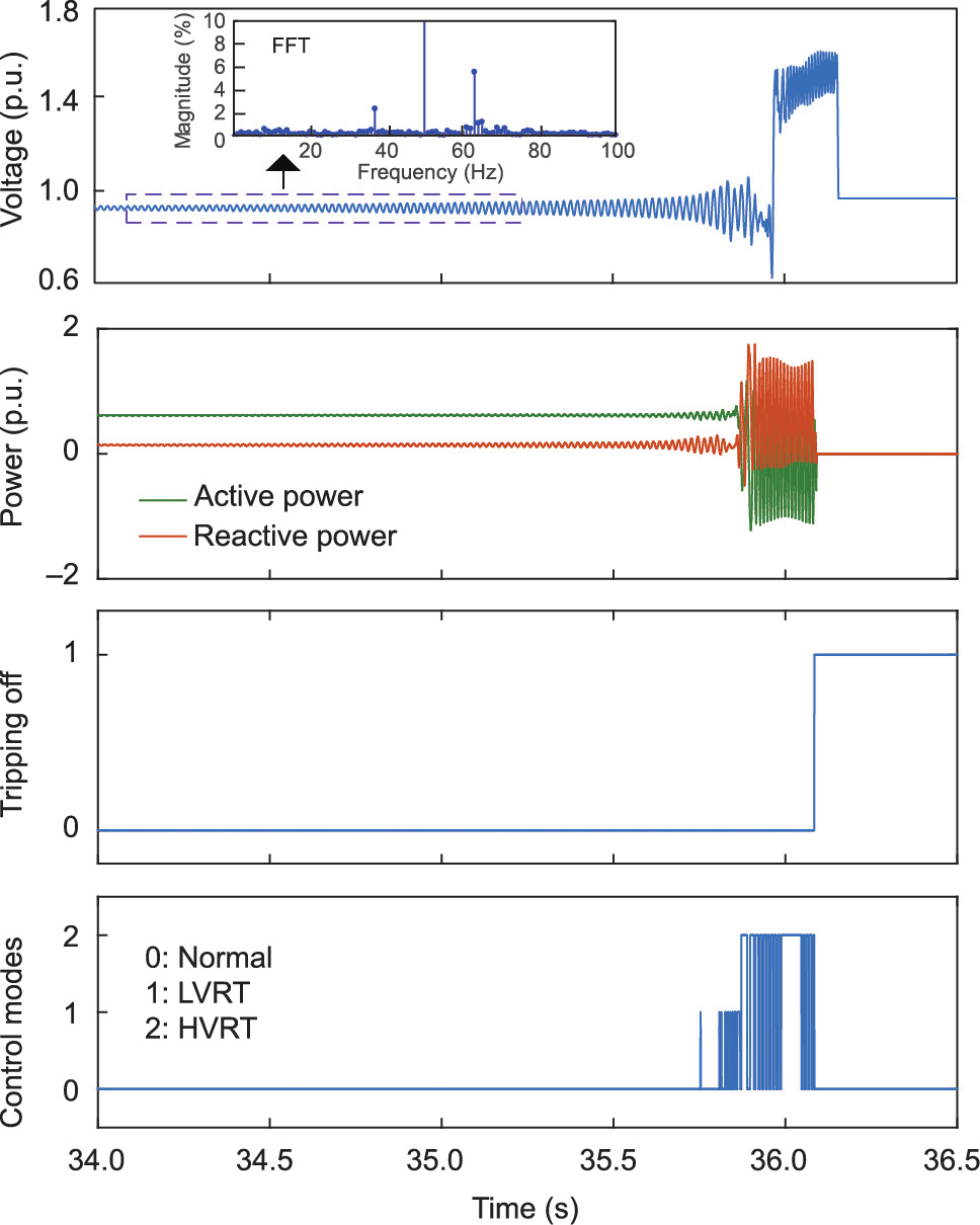
Fig. 10. PV tripping off caused by the chain reaction between broadband oscillation and transient over-voltage.
In order to improve the stability of HPPESs, the control of power electronic devices should be designed in such a way as to satisfy the requirements of the steady-state and transient characteristics simultaneously. According to the coupling between steady-state and transient stability, the design of controllers should strike a balance between them. For example, the control performance of the PLL influences both the broadband oscillation and the transient over-voltage [65]. A reduction of the control bandwidth of the PLL is beneficial in order to improve the steady-state stability of the system. However, reducing the control bandwidth seriously restricts the transient characteristics of the fault ride-through, leading to transient over-voltage.
《4. Research methods》
4. Research methods
To deal with the complexity of an actual HPPES, we propose the analytical methods of small-signal impedance analysis and EMT simulation to solve the steady-state and transient stability issues. In this section, we explain the application of these two methods to analyze broadband oscillation and transient over-voltage, and compare the characteristics of the two methods.
《4.1. The small-signal impedance analysis method》
4.1. The small-signal impedance analysis method
The eigenvalue analysis method based on state-space equations is usually adopted to analyze oscillation issues in a traditional power system. The impedance analysis method based on smallsignal modeling [66,67] can effectively analyze the oscillation in a DC system and has been extended to three-phase AC systems [68–72]. As the system is equivalent to a two-port network, the small-signal impedance analysis method has a clear physical concept and is applicable to an oscillation analysis combined with the Nyquist stability criterion.
However, a complex HPPES presents several challenges to the practical application of the impedance analysis method:
• It is difficult to obtain the analytical impedance model, due to the confidentiality of core control strategies and parameters in renewable energy converters and HVDC.
• The equivalent system impedance is difficult to determine, due to the complex frequency-coupling characteristics among the large number of various power electronic devices in an HPPES.
• The Nyquist stability criterion is too conservative to apply to the dynamic changes of impedance under various operating conditions. The Nyquist curve must pass through the (–1, j0) point and cannot cover the stability problem along with the wide range of power fluctuation of renewable energy converters.
To address the challenges listed above, we propose the use of the impedance modeling method and stability criterion for a complex HPPES with a system equivalent to a two-port network. The main contributions of this research are as follows:
(1) Impedance scanning of power electronic devices: An impedance scanning platform based on a control CHIL simulation is established in order to determine the actual impedance characteristics of power electronic devices effectively. To eliminate the influence of simulation step size, interface delay, and switch model parameters on the measurement accuracy, an impedance measurement correction method is proposed [73]. Based on this method, an impedance model library containing 253 types of renewable energy converters has been established that covers 80% of the total installed capacity in China. In addition, the impedance characteristics of the LCCs and VSCs produced by mainstream manufacturers in China have also been scanned.
(2) Impedance modeling of a multi-port network: Considering the coupling characteristics of large quantities of various power electronic devices and the frequency-dependent characteristics of the collection network, a broadband coupling impedance network modeling method for an HPPES has been proposed in Refs. [74,75]. The system is divided into two (or more) mutual coupling impedance networks, and the topology is consistent with the actual power grid, as shown in Fig. 11. Using the impedance network model and multi-variable frequency domain theory, a multi-port transfer function matrix model based on the multi-section division of the system is established. The relationship between the impedance network and the multi-variable feedback system is investigated, which lays a foundation for applying electrical network oscillation mode analysis to broadband oscillation stability analysis.
《Fig. 11》

Fig. 11. The broadband coupling impedance network model.
(3) Stability criterion: To overcome the limitations of the classical Nyquist stability criterion, the theoretical impedance of renewable energy converters is established, considering the outer-loop power control. This can specifically describe how the impedance characteristics are influenced by the operating points corresponding with wind speed and solar irradiance. A maximum peak Nyquist criterion is proposed to accurately analyze the broadband oscillation stability of the HPPES [76]. The impact significance of the operating points on the impedance characteristics varies for different frequency bands. Consequently, different stability margins are formulated for different frequency bands (Band I–Band IV in Fig. 2), based on the statistics of the established impedance model library.
Based on the contributions of the impedance scanning, network modeling, and stability criterion of an HPPES, a relevant standard has been formulated for the safe and stable operation of HPPESs [77], in which the model requirement, testing method, operation condition, stability margin, and other aspects are specified.
《4.2. EMT simulation technology》
4.2. EMT simulation technology
The phasor model is based on the fundamental electrical quantities of voltage and current, which makes it difficult to use this model to describe the broadband oscillation and transient overvoltage process within 20 ms in an HPPES. The EMT model is built according to the main circuit, control structure, and parameters of the actual power electronic devices and accurately describes the dynamics of the broadband oscillation and transient process of over-voltage in an HPPES.
There are two technical challenges in EMT modeling. The proposed CHIL simulation in Section 3 can accurately reflect the EMT characteristics of a single renewable energy unit, but a CHIL simulation of thousands of units is impossible due to the limitation in physical input–output (I/O) interfaces. On the other hand, ultra-high processing resources are required for a microsecond small-step EMT simulation of many power electronic devices in an HPPES.
To address these issues, relying on the State Key Laboratory of the Operation and Control of Renewable Energy and Storage Systems, our team has built an EMT simulation platform for largescale renewable energy transmitted by HVDC. Hence, real-time EMT simulation with accurate and duplicable unit models and equivalent plant models can be carried out to describe the EMT process of an HPPES, as outlined below, which provides an effective means for analyzing transient stability issues.
4.2.1. EMT modeling of renewable energy units
An EMT simulation model of renewable energy units is established, in which the source code is packaged as control modules instead of the real controllers. The encapsulated model can be used for the simulation of large numbers of units. Verification of the EMT response characteristics under onsite prototype testing (PTT), CHIL simulation, and EMT simulation of the dynamic link library (DLL) is carried out to ensure the accuracy of the digital simulation model, as shown in Fig. 12. First, the CHIL simulation is set as the calibrated benchmark according to the results of PTT. Considering the limitation of the operating conditions in PTT, the other operating conditions that cannot be accomplished in PTT are fulfilled by CHIL simulation to verify the EMT response of the DLL models, such as the transient over-voltage of LCC commutation failure and oscillation in a weak grid.
《Fig. 12》

Fig. 12. EMT response characteristics verification under PTT, CHIL, and DLL simulations.
4.2.2. EMT modeling of renewable energy plants
The accurate modeling of renewable energy plants should consider not only the total capacity but also the line impedance between units. However, the line impedance from each renewable energy unit to the common coupling point of the plant is different. Therefore, an EMT equivalent plant modeling method is proposed to represent the detailed plant model. All the units in one plant are divided into several groups according to the size of the line impedance magnitudes. The line impedance in each group is taken as the typical value, and multiple units are replaced by an equivalent one with the total capacity. Fig. 13 compares the broadband impedance and transient characteristics between the detailed model and the equivalent model of the PV station. The PV station, which has a total capacity of 30 MW, is composed of 48 PV inverters of 0.64 MW each, which is equivalent to four units with the proposed EMT modeling method.
《Fig. 13》

Fig. 13. Broadband impedance and transient characteristics between the detailed model and equivalent model of a PV station. (a) Impedance characteristics; (b) transient characteristics.
Eventually, an EMT real-time simulation platform for largescale renewable energy transmission through LCC/VSC-HVDC was built based on the actual control and protection equipment. The platform provides an effective means for broadband oscillation and transient over-voltage issues. The feasibility and accuracy of the EMT real-time simulation platform have been validated by recurrences of practical incidents, such as transient over-voltage under DC commutation failure of LCC-HVDC and AC short-circuit fault of VSC-HVDC, as shown in Fig. 14.
《Fig. 14》

Fig. 14. Comparison between the EMT simulation and the field test under large disturbance tests. (a) DC commutation failure of LCC-HVDC; (b) AC short-circuit fault of VSCHVDC.
《4.3. The combination of small-signal analysis and EMT simulation》
4.3. The combination of small-signal analysis and EMT simulation
The small-signal method can be used for the steady-state stability analysis of an HPPES under multiple operating conditions, including different active power generation and different numbers of grid-connected units. The system stability can be evaluated under specific conditions and quantitatively analyzed by calculating the stability margin. Furthermore, through the sensitivity analysis, the small-signal analysis method can provide guidelines for system stability improvement by optimizing the impedance characteristics of power electronic devices, which will be discussed in Section 5.
EMT simulation can provide models of the renewable energy units and accomplish impedance scanning for small-signal analysis. For conditions with an insufficient margin, EMT simulation can verify the stability and determine the oscillation amplitudes. Moreover, it can reproduce the oscillation incidents and cascaded transient over-voltage induced by oscillations in the HPPES. In addition, EMT simulation can accurately describe the transient switching process of control modes from steady-state operation to the fault ride-through mode, because it is capable of describing the nonlinear characteristics of power electronic devices. For the fault analysis of the system, EMT simulation can reproduce the transient characteristics in a short duration, even within 20 ms.
The efficiency of small-signal analysis and the accuracy of EMT simulation are highlighted by the complementarity of the two methods when used to solve the steady-state and transient issues in an HPPES, thereby ensuring the safe and stable operation of the power system. For the future power system, the complementarity of the two methods will show more significant advantages.
《5. Project practice》
5. Project practice
Based on the theoretical analysis, several typical scenarios are selected to explain how the analytical methods of small-signal impedance analysis and EMT simulation are applied to solve practical problems. The following section describes two oscillation cases of renewable energy integrated with LCC-HVDC and VSCHVDC systems and one transient over-voltage case of renewable energy integrated with LCC-HVDC. The causes of accidents are deduced according to their mechanisms, and the corresponding solutions are proposed in order to suppress the broadband oscillations and transient over-voltage.
《5.1. Broadband oscillation》
5.1. Broadband oscillation
5.1.1. Renewable energy transmitted by LCC-HVDC
Xinjiang is rich in wind power resources, with the installed capacity of the WTs in Hami exceeding 18.8 GW. LCC-HVDC transmission from Xinjiang to Henan is the main corridor for exporting renewable energy in the Hami region, sending renewable energy from northwest to central region of China. However, several severe oscillation incidents occurred in PMSG wind farms in July 2015 and in DFIG wind farms in May 2017, resulting in large-scale tripping off of WTs. The layout of the wind farms at the sending-end system is shown in Fig. 15.
《Fig. 15》

Fig. 15. Layout of the wind farms at the Xinjiang–Henan LCC-HVDC sending-end system.
According to Section 3.1, the oscillation occurs between the WTs and the weak AC grid. To analyze the oscillation, the positive-sequence impedance of the renewable energy converters is obtained by means of impedance scanning, while the impedance of the weak grid (SCR = 1.5) is calculated using impedance modeling of the multi-port network, as mentioned in Section 4.1. The results shown in Fig. 16 represent the negative damping characteristics of the WTs and the insufficient system stability margin in the super-synchronous frequency band, respectively. Through the maximum peak Nyquist criterion, based on an analysis of the ratio between AC grid impedance and PMSG impedance, oscillation occurs between the PMSG and the weak AC grid at 75 Hz in a positive sequence. A Fourier analysis of the recorded data reveals that there is another oscillation component of 25 Hz, which confirms the mentioned frequency-coupling mechanism. Similarly, oscillation occurs between the DFIG and the weak AC grid at positivesequence 65 Hz with the coupled component at 35 Hz.
《Fig. 16》

Fig. 16. PMSG impedance characteristics and Nyquist criterion. (a) Impedance characteristics; (b) Nyquist criterion.
In order to solve the oscillation issue, the magnitude and phase characteristics of the converter impedance should be reshaped, typically through optimization of the control parameters or modification of the control structure. More specifically, the impedance characteristics in the super-synchronous band of the PMSG are dominated by the PLL and will be affected by the current control. Consequently, the PMSG impedance can be reshaped to eliminate the oscillation risk by optimizing the control parameters for the PLL and the current loop [65]. In addition, according to Ref. [61], the negative damping characteristics of the DFIG in the supersynchronous frequency band are mainly caused by the overlapping effect of the outer-loop power control and inner-loop current control, as shown in Fig. 2. Therefore, the phase characteristics of the DFIG’s impedance can be boosted by modifying the outer power control strategy so as to eliminate the oscillation risk, as shown in Fig. 17. The proposed impedance-reshaping technology was applied to the wind farms in Hami [78], and there has been no oscillation incident since October 2017.
《Fig. 17》

Fig. 17. DFIG impedance characteristics and Nyquist criterion. (a) Impedance characteristics; (b) Nyquist criterion. Z: impedance.
5.1.2. Renewable energy transmitted by VSC-HVDC
The Zhangbei project is a multi-terminal VSC-HVDC project that effectively supported the 2022 Beijing Winter Olympics with a 100% clean-energy power supply. Renewable energy converters are integrated into the islanded VSC-HVDC at the Zhongdu, Zhangbei station (rated capacity: 3 GW). Since February 2021, with the total installed capacity of the renewable energy converters exceeding 1.4 GW, several oscillations at 58 Hz have been recorded. The layout of the renewable energy plants is shown in Fig. 18. A Fourier analysis of the fault current and fault voltage reveals that the oscillation component is a negative-sequence component.
《Fig. 18》

Fig. 18. Layout of the renewable energy plants in Zhangbei.
According to Section 3.1, the oscillation occurs between the renewable energy converters and the VSC. The negative-sequence impedance of the renewable energy converters and the VSC is acquired by impedance scanning, as shown in Fig. 19(a). The negative-sequence impedance of the VSC presents inductive negative damping characteristics near 58 Hz, while that of the renewable energy converters presents capacitive characteristics. The magnitudes of the two impedances intersect and the phase difference is close to 180, indicating an insufficient stability margin. Through the maximum peak Nyquist criterion in Fig. 19(b), the negative-sequence oscillation of the system occurs at 58 Hz; moreover, a 158 Hz positive-sequence coupling component is generated. In summary, the negative damping characteristic of the VSC is the main factor causing oscillation.
《Fig. 19》
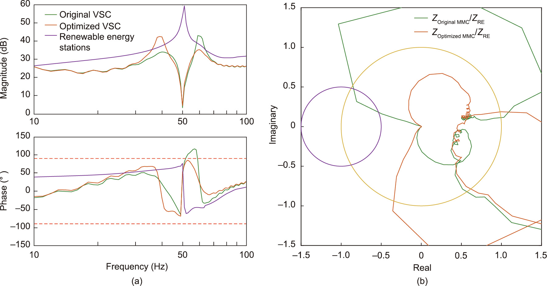
Fig. 19. VSC impedance characteristics and Nyquist criterion of the original and the optimized control. (a) Impedance characteristics; (b) Nyquist criterion. RE: renewable energy.
Based on the impedance characteristics reshaping method, the capacitive negative damping characteristics of the negativesequence impedance in the VSC around the super-synchronous frequency band are eliminated through the modification of the AC voltage outer-loop control. Fig. 19 shows that the stability margin of the system is improved after the impedance optimization of the VSC, eliminating the risk of system oscillation. On 20 July 2021, field tests on oscillation recurrence were carried out at Zhongdu, Zhangbei station. System oscillations were eliminated after the proposed oscillation suppression strategy was employed, as shown in Fig. 20, which completely verified the effectiveness of the analysis method and suppression strategy. Since then, there has been no oscillation incident at the station.
《Fig. 20》
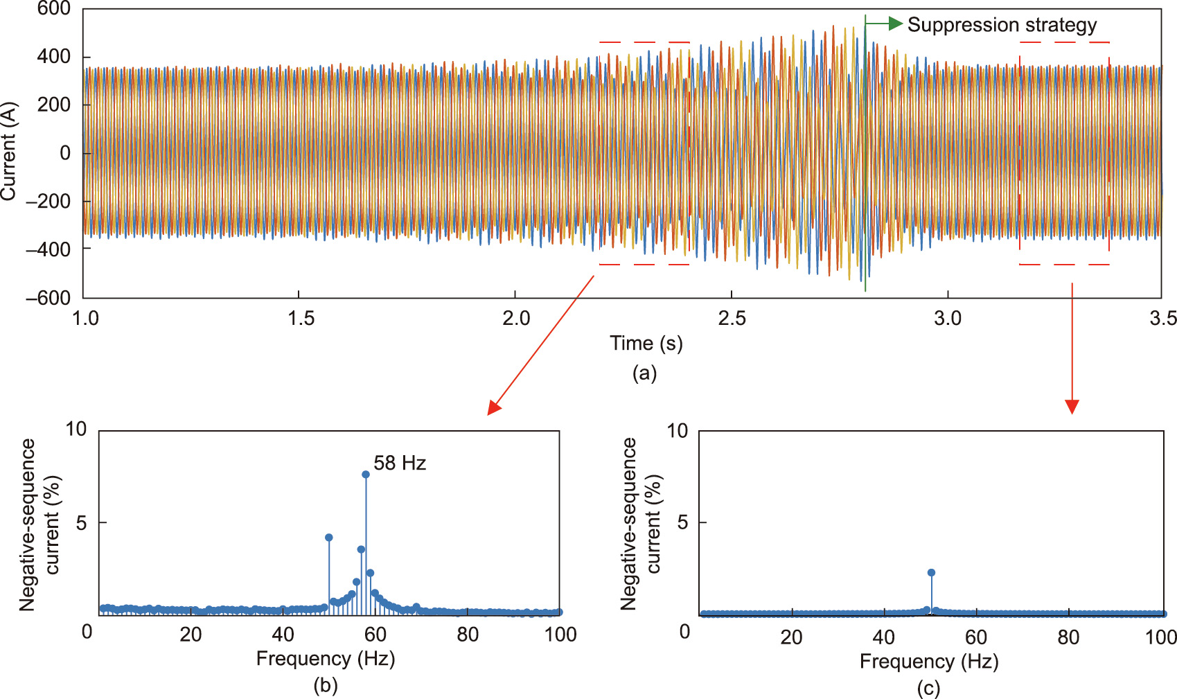
Fig. 20. The field test of oscillation recurrence and suppression. (a) Current of oscillation reproduction and suppression; (b) FFT analysis of oscillation reproduction current; and (c) FFT analysis of oscillation suppression current.
《5.2. Transient over-voltage》
5.2. Transient over-voltage
Gansu Province has abundant wind power resources, and a large-scale wind power base with an installed capacity greater than 7.5 GW has been built in Jiuquan. The ±800 kV/8 GW Gansu–Hunan LCC-HVDC transmission project shown in Fig. 21 was put into operation in 2017. In order to analyze the transient stability under a grid fault of the power system, an EMT simulation platform consisting of wind farms and the LCC-HVDC system was constructed. The accuracy of the simulation model was ensured by the consistency of EMT responses and PTT results, as mentioned in Section 4.2. Based on the EMT simulation results, there is a risk of transient over-voltage under LCC commutation failure and AC short-circuit fault, especially with an increase of the transmission power of the LCC-HVDC.
《Fig. 21》

Fig. 21. Layout of wind farms at the Gansu–Hunan LCC-HVDC sending-end system.
In order to solve the transient over-voltage issue, a detailed analytical model of the transient response of renewable energy converters was established [62]. Based on the analytical model, the slow control response introduced by the improper control of renewable energy converters will cause transient over-voltage during the transient process, which coincides with the conclusion in Section 3.2. In addition, the effect of the flux characteristics in the DFIG on transient over-voltage has been elaborated. During the transient process, the transient over-voltage is more severe in the PMSG, because the flux conservation of the DFIG has an inherent suppression effect [78]. Moreover, the suppression effect is more significant, as the duration of the transient process is short.
Based on the theoretical analysis, a transient over-voltage suppression strategy was proposed based on modifying the control structure and the optimization of controller parameters [79]. More specifically, a virtual flux control was proposed and applied to the PMSG and PV inverters to improve the transient response of the reactive power. In addition, the response speed of active power control, reactive power control, and PLL during the transient process was improved by the optimization of the parameters. Consequently, the EMT simulation model was modified according to the proposed suppression strategy, and the results of the EMT simulation platform showed that no transient over-voltage occurs under DC commutation failure and AC short-circuit fault.
According to the results obtained by our research team, a relevant standard was formulated to guide the modification of the practical HVRT strategy of renewable energy converters [80]. The effectiveness of the suppression strategy was verified by field testing in Gansu Province, whose results in Fig. 22 showed no transient over-voltage of renewable energy converters under large grid disturbances [81]. Furthermore, the standard has been disseminated throughout China and has been applied to several renewable energy plants at the sending end of HVDC transmission projects, such as the Inner Mongolia–Jiangsu and Qinghai–Henan LCC-HVDC projects, which has improved the stability of the power system.
In summary, considering the interaction of broadband oscillation and transient over-voltage issues, optimization of control parameters and modification of control structure should be combined to solve steady-state and transient issues in the future power system.
《Fig. 22》

Fig. 22. Field test of transient over-voltage under a large grid disturbance. (a) DC commutation failure; (b) AC short-circuit fault.
《6. Conclusion and prospect》
6. Conclusion and prospect
With the development of large-scale renewable energy, an HPPES gradually forms at the HVDC sending end. New stability issues occur, including broadband oscillation and transient over-voltage. To address these issues, this paper revealed the mechanisms of broadband oscillation and transient over-voltage, and proposed research methods combining small-signal impedance analysis and EMT simulation. The successful solution of broadband oscillation and transient over-voltage issues in several practical projects has verified the proposed methods. The following conclusions can be drawn based on the main contributions of this paper.
(1) The control of power electronic devices is the main reason for broadband oscillation and transient over-voltage in an HPPES, which includes multi-loop control and the switching of control modes. The negative damping characteristics of power electronic devices are distributed in a wider frequency range due to the multi-loop control, which causes an extension of the oscillation frequency. Multi-loop control and the slow response of switching the control modes induces transient over-voltage, causing the tripping off of renewable energy converters. Moreover, as the grid strength is weak, broadband oscillation and transient overvoltage interact with each other more significantly.
(2) The advantages of small-signal impedance analysis and EMT simulation are complementary in the analysis of broadband oscillation and transient over-voltage. Small-signal impedance analysis can be used to efficiently analyze the system stability margin under various operating conditions. In addition, EMT simulation can accurately reproduce the nonlinear characteristics and transient process under specific conditions. For the future power system with a high penetration of power electronic devices, the complementarity of these two methods will lead to more significant advantages.
(3) Two types of stability issues are caused by incompatibility between the design principles of controllers and the actual characteristics of an HPPES. The interaction effects among renewable converters, LCCs/VSCs, and a weak grid in an HPPES are not comprehensively considered in the conventional design principles of controllers. In this paper, the control structure and controller parameters were redesigned, based on the practical characteristics of HPPESs. As a result, the broadband oscillation and transient over-voltage issues were solved effectively, as has already been verified through several practical projects.
As the future power system will face more complex stability problems and operational challenges, the analysis of stability mechanisms and relevant research methods should keep pace with the development of the power system over time. We suggest future research in the following aspects:
(1) For the larger-scale utilization of renewable energy in the future, it is necessary to develop hybrid HVDC technology combined with LCCs and VSCs. The capabilities of large transmission capacity, island voltage establishment, fault current limiting, and the independent control of active and reactive power can be further exploited. Furthermore, DC grid construction based on HVDC is a future trend for collecting large-scale renewable energy in many regions, including multi-terminal HVDC. A DC grid is beneficial for realizing coordination of the power supply, grid network, load and energy storage, and peak-valley adjustment of renewable energy generation. Therefore, more advanced control technologies should be developed for large-scale renewable energy transmission through HVDC.
(2) Considering the rapid expansion of renewable energy generation based on power electronic devices, the stability issues of the future power system may spread from the local to the global system. For example, in a point-to-point HVDC system, the receiving-end performance may affect the stability at the sending end. In a multi-terminal HVDC system, a system fault at any terminal may lead to the stability risk of other terminal systems. Given these issues, the analysis of the stability mechanism requires further investigation.
(3) For the construction of the future power system, the design principle should include the requirements not only for the grid characteristics but also for the control of power electronic devices. Furthermore, the control in power electronic devices should be designed with normalized structures. The formulation of relevant standards should also be accelerated, including the requirements for grid connection and operation.
《Acknowledgments》
Acknowledgments
This work is funded by National Key Research and Development Program of China (2021 YFB2400500). The authors would like to thank Guoqing He, Haijiao Wang, Yuntao Xiao, and Yuqi Duan for their contributions in research review, field test verification, and data analysis.
《Compliance with ethics guidelines》
Compliance with ethics guidelines
Weishang Wang, Guanghui Li, and Jianbo Guo declare that they have no conflict of interest or financial conflicts to disclose.


 京公网安备 11010502051620号


