

《1 Introduction》
1 Introduction
Transportation plays a significant role in energy consumption and carbon emissions around the world, and it is a key factor that contributes to growth in oil consumption. Developing energy-saving and environmentally friendly alternative energy vehicles can not only reduce oil imports and carbon emissions, but also help to achieve the transformation and upgrading of the automobile industry in China. As a type of alternative energy vehicle, the fuel cell vehicle has attracted increasing attention from governments, enterprises, and research institutions because of its long range, fast fueling, and compatibility with renewable energy. Governments of many countries have introduced incentives and financial subsidies to promote the establishment of a market for fuel cell vehicles. Fuel cell vehicles have seen a gradual transition from large-scale demonstration to commercial availability. Certain fuel cell vehicles have taken the lead in commercialization and have a similar level of performance as conventional fuel vehicles, such as the Toyota Mirai, Honda Clarity, and Hyundai Nexo. The power of fuel cell passenger vehicles is generally around 100 kW, and the power of fuel cell commercial vehicles ranges from 30 to 200 kW. The FCV80 released by SAIC Maxus Automotive Co., Ltd. (SAIC Maxus) was the first fuel cell vehicle available for purchase in China. Other automakers have since launched fuel cell products, most of which are commercial vehicles. The power of domestically-produced fuel cell stacks for vehicles in China is between 30 and 50 kW, which is generally lower than those found in similar international fuel cell vehicles. The reason is that current domestically available fuel cell products appear to meet the threshold for financial subsidies. However, it seems that high specific power fuel cell stack technology in China has not reached the advanced international level, whether imported or produced locally. Therefore, it is necessary to increase the power density of domesticallyproduced fuel cells. In particular, high power density is required to operate a fuel cell stack that fits in the limited space of a passenger car. In addition, increasing the power density can reduce the need for fuel cell materials, components, and other hardware, thereby significantly reducing the cost of fuel cells.
The power density of a fuel cell can be increased in two ways: improving performance and reducing volume. In terms of performance, analysis of the fuel cell polarization curve (Fig. 1) shows that reducing activation polarization, ohmic polarization, and mass transfer polarization can improve the performance of fuel cells. These reductions in turn require improvements in key materials such as catalysts, membranes, and bipolar plates, as well as ensuring the consistency of the stack. In terms of volume, it is necessary to reduce the thickness of the hardware, such as bipolar plates, and improve its integration. Based on theoretical analysis and practical engineering experience, this paper explores effective ways to increase power density in order to provide a reference for researchers and engineers in this field.
《Fig. 1》
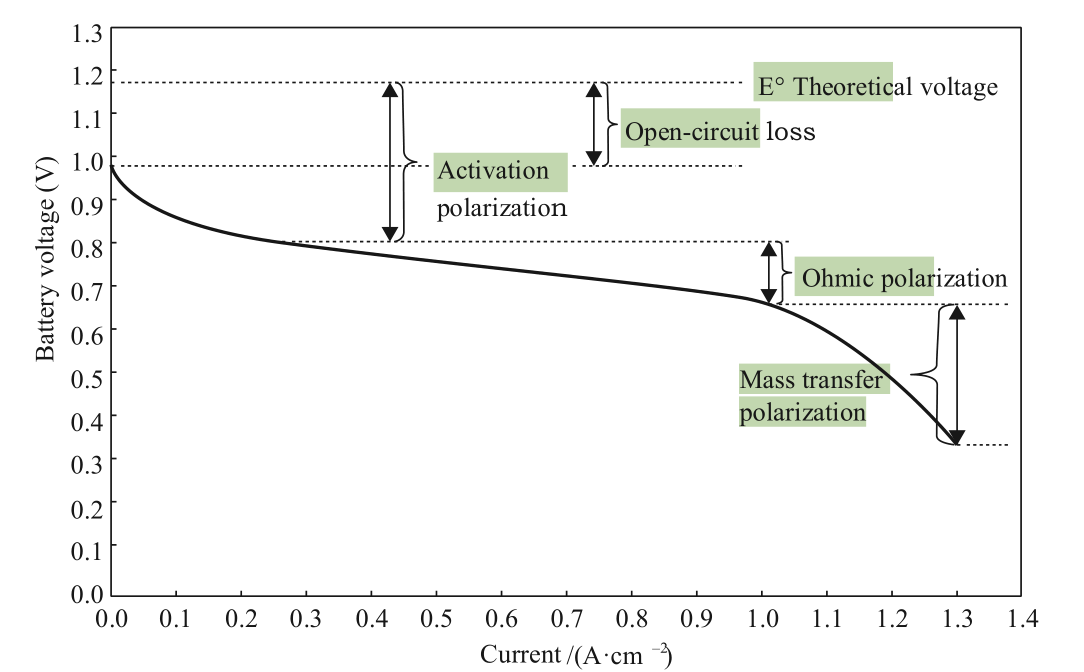
Fig. 1. Typical polarization curve of a fuel cell.
《2 Highly active and stable catalysts and electrodes》
2 Highly active and stable catalysts and electrodes
As can be seen from the fuel cell polarization curve, in order to improve the performance of a fuel cell, it is vital to first reduce the activation polarization, which is closely related to the activity of the catalysts. In the reaction process of fuel cells, the exchange current density of the oxygen reduction reaction (ORR) is much lower than that of the hydrogen oxidation reaction (HOR), so polarization losses mainly come from the cathode side (air side). Therefore, research should focus on improving the activity of catalysts on the cathode side. At present, the most commonly used commercial catalysts in proton exchange membrane fuel cells (PEMFCs) are platinum-carbon (Pt/C) catalysts. These are supported catalysts that are dispersed by Pt nanoparticles onto carbon powder (such as XC-72). Tests have shown that this commercial catalyst has some shortcomings in terms of activity and stability. Table 1 shows an index of technical targets for catalysts released by the United States Department of Energy (DOE). Researchers have explored approaches to prepare highly active and stable catalysts using a variety of methods, including Pt crystal plane control, Pt-M alloy catalysts, Pt-M coreshell catalysts, Pt surface modification, and single-atom Pt catalysts [1]. Based on these studies, only Pt-M alloy catalysts can be used in practice.
《Table 1》
Table 1. DOE technical targets for catalysts.

A Pt-M catalyst is an alloy catalyst formed by Pt and a transition metal. The electronic and geometrical effects of the transition metal catalyst on Pt can improve both the stability and mass specific activity of the catalyst. In addition, this approach can reduce the amount of precious metals needed, which greatly lowers the cost of the catalyst. Pt-Co/C, PtFe/C, Pt-Ni/C, and other binary alloy catalysts [2,3] have shown good activity and stability. Chen et al. [4] prepared highly active and stable Pt3Ni nanocage catalysts by taking advantage of the structural characteristics of platinum-nickel alloy nanocrystals. The mass specific activity and area specific activity of the catalysts increased by 36 times and 22 times, respectively. Toyota Motor Corporation disclosed that the commercialized fuel cell vehicle Mirai used Pt-Co alloy catalysts, which increased its catalyst activity by 1.8 times. The use of the Pt3Pd/C catalyst developed by the Dalian Institute of Chemical Physics of the Chinese Academy of Sciences (DICP) has been verified in fuel cell stacks, and it can replace current commercial catalysts due to its high performance. In addition, DICP also developed ultra-small PtCu alloy catalyst [5], whose mass specific activity is 3.8 times that of current Pt/C. Furthermore, PtNi alloy nanowire catalyst [6] has a mass and area specific activity of 2.5 and 3.3 times of that of Pt/C, respectively (Fig. 2). This has shown its prospects of future applications.
《Fig. 2》
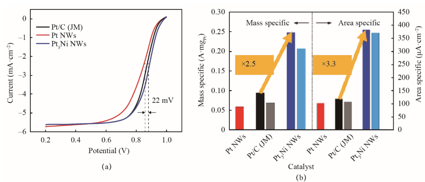
Fig. 2. PtNi alloy nanowire catalyst.
For Pt-M catalysts, it is necessary to address the dissolution of transition metals that occurs under fuel cell operating conditions. Metal dissolution not only reduces catalyst activity, but also results in membrane degradation caused by the resulting metal ions. In this regard, further research is required to improve the stability of Pt-M catalysts. In order to improve the stability of Pt alloy catalysts, it is necessary to optimize system control strategies for reducing the degradation of the catalyst.
In addition to improving catalyst activity and reducing activation polarization, the electrode structure is another factor to be addressed to improve performance. An electrode usually consists of a diffusion layer and a catalyst layer. A properly designed electrode structure is conducive to reducing ohmic polarization and mass transfer polarization. The development trendsfor electrodes are to further reduce the thickness of the catalyst layer, increase the mass transfer of the gas diffusion layer, promote the mass transfer process, and increase the maximum current density of the electrode so that the working current can reach 2.5–3 A/cm2 or higher. The fuel cell stack in the Toyota Mirai has a thin low-density diffusion layer, which can significantly reduce ohmic polarization and mass transfer polarization, and significantly improve the working current density.
《3 Enhanced composite membrane》
3 Enhanced composite membrane
As can be seen in Fig. 1, the performance of a fuel cell can be improved by increasing the activity of the catalyst and reducing the activation polarization. As the current increases, the slope of the straight-line segment of the voltage-current curve is mainly due to the ohmic polarization of the membrane. In order to improve performance, current automotive proton-exchange membranes are made thinner, from tens of microns to a dozen microns or less, which reduces the ohmic polarization of the proton transfer. However, a thinner membrane is more susceptible to mechanical damage and chemical degradation under operating conditions in vehicles (such as from dynamic changes in operating pressure, dryness and humidity, and temperature). A composite membrane is used widely. It uses the resin of a homogeneous membrane compounded with organic or inorganic materials, which improves some of its functions. Based on this, enhanced composite membranes appear to be the main solution for the application of thin membranes. Enhanced composite membranes not only ensure the performance of the membranes but also enhances their mechanical strength and chemical durability. The technical approach to develop these composite membranes consists of two aspects: mechanical enhancement and chemical enhancement (Fig. 3).
《Fig. 3》
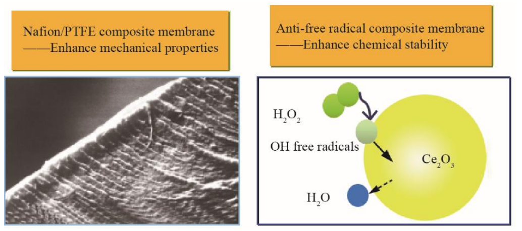
Fig. 3. Technical approach of enhanced composite membranes.
For mechanical enhancement, porous membranes (such as porous polytetrafluoroethylene (PTFE)) or fibers have been used as skeletons to be reinforced and impregnated in perfluorosulfonic acid resin. The resin distributed within the porous membranes ensures proton conduction. Porous substrate membranes can improve the strength and dimensional stability of the membrane, such as the composite membrane of W. L. Gore & Associates [7], the patented Nafion/PTFE enhanced composite membrane of the DICP [8], and the carbon nanotube enhanced composite membrane [9]. Chemical enhancement is used to prevent chemical attenuation caused by free radicals during the electrochemical reaction. Adding a radical scavenger can decompose and remove free radicals during the reaction process and improve durability. DICP [10] prepared a composite membrane by adding 1 wt% of CsxH3-xPW12O40/ CeO2 nano-dispersed particles into a Nafion membrane. The free radicals were quenched by the reversible redox properties of the variable valence metals in CeO2. Introducing CsxH3-xPW12O40 has also ensured good protonic conduction and has strengthened the catalytic decomposition of H2O2. Nanjing University added antioxidant vitamin E [11] to its PEM. Its main ingredient α-tocopherol can capture and convert free radicals into an oxidized state, which can then be reduced with permeated hydrogen, thus improving the life of the fuel cell.
《4 Bipolar plate flow field and materials》
4 Bipolar plate flow field and materials
The bipolar plate is an important part of a fuel cell that supportsthe membrane electrode assembly (MEA). It conducts electrons, distributes reaction gas, and removes product water. In terms of the performance of the fuel cell, bipolar plates can affect mass transfer polarization and ohmic polarization.
For reducing ohmic polarization, a bipolar plate generally has good electrical conductivity. At present, commonly used bipolar plates include graphite materials, graphite composites, and metal materials. These three types of bipolar plate materials all have good electrical conductivity, but there are some special considerations for their application in different scenarios. A pure graphite bipolar plate has good electrical conductivity, but its flow channel is usually mechanically carved. This is a first-generation bipolar plate with low processing efficiency and high cost, which has been gradually replaced by other materials. Graphite composites are usually made of carbon powder and resin in a specific ratio, and the flow field can be created through molding, which is low cost. However, adding resin and other non-conductive materials may affect its conductivity to a certain extent, especially when the current density is high. Therefore, the conductivity of graphite composites needs to be improved while ensuring the compactness and processability of bipolar plates.
Metal is a good conductor of electricity and heat, and it is more and more widely used as a material for bipolar plates of PEMFCs. It is particularly preferred when the high power density of the fuel cell is required for use in a limited space (such as passenger cars). Thin-metal bipolar plates have become the top choice for increasing the power density of fuel cells due to their thinness and inherent good conductivity. At present, most major automotive companies use metallic bipolar plates, such as Toyota Motor Corporation, Honda Motor Co., Ltd., and Hyundai Motor Group. The technical challenge of metallic bipolar plates is that they need corrosion resistance in a fuel cell environment (to protect from acid, electric potential, humidity, and heat) and to be compatible with other components and materials. At present, commonly used metal materials for bipolar plates are stainless steel and titanium with a surface coating. A lot of academic research has been done domestically and internationally on the corrosion-resistant surface coating of stainless-steel bipolar plates in a fuel cell. The coating material needs to have both of corrosion resistance and electrical conductivity. Typical coating materials are shown in Table 2. In general, materials eligible for surface coating can be divided into three types: metals (such as precious metals), metal compounds, and carbon coatings. Precious metals such as gold, silver, and platinum can be used for coatings. Despite their high costs, they are still used in special areas given their superior corrosion resistance and contact resistance similar to graphite. In order to reduce costs, the thickness of the layer for coating is as thin as possible, and pinholes should be avoided. Metal compound coatings are currently the most studied scheme for surface coatings. Compounds such as Ti-N, Cr-N, and Cr-C [12–14] have shown great application value. In addition to metalbased coatings, some studies have explored carbon-based coatings for metallic bipolar plates, such as graphite, conductive polymers [15] (polyaniline, polypyrrole), and diamond-like membranes. The patented technology (US2014356764) of Toyota Motor Corporation offers a method for surface coating of bipolar plates using highly conductive hybrid SP2 orbitals in a matrix of amorphous carbon.
《Table 2》
Table 2. Comparison of coating materials for metallic bipolar plates

The techniques of coating preparation are also an important factor in improving the coating materials’ corrosion resistance and electrical conductivity. The coating needs to be free of pinholes and cracks; pinholes on the surface coating layer of metallic bipolar plates are a common problem. Pinholes appear due to a discontinuous phase that leads to particle deposition during the preparation process, which can induce electrochemical corrosion of the base material through pinholes when the fuel cell is in operation. Moreover, as the linear expansion coefficients of the metal for coating and the matrix are different, micro-cracks may be caused by thermal cycling in each operating mode. This issue can be alleviated by adding a transition layer. DICP and the Dalian University of Technology conducted research on the surface modification of metallic bipolar plates. They adopted a pulse bias arc ion plating method to prepare a multilayer membrane structure [16], and the results have shown that the multilayer structure can improve the conductivity and corrosion resistance of bipolar plates.
Reasonable design and layout of the bipolar plate flow field help reduce mass transfer polarization and improve performance at high current densities, thereby increasing the power density of the stack. Toyota Motor Corporation introduced a new design concept of a 3D flow field in the Mirai fuel cell stack (Fig. 4), which changed the traditional 2D flow field design of serpentine and parallel grooves. There are the fluid components perpendicular to the gas diffusion layer and the catalyst layer. The reactants and products do not rely solely on concentration diffusion to reach and separate from the reaction interface, but have the forced convection, which greatly improves the mass transfer of the fuel cell and, therefore, the performance. In addition, this 3D flow field has a certain capacity for water storage, which is conducive to adjusting the humidity of the fuel cell during operation and, therefore, can improve the performance of the fuel cell by maintaining low humidification.
《Fig. 4》
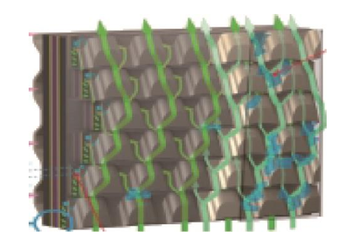
Fig. 4. Schematic of 3D flow field of Mirai fuel cell stack.
Simulation [17] further confirms that the 3D flow field enhances the water removal capacity of the flow channel and diffusion layer (Fig. 5; a zero-water-saturation zone occurs in the 3D flow field in the diffusion layer). In addition, the forced convection of oxygen in the catalyst layer has been increased, especially at high current density. This greatly improves performance compared with the conventional 2D flow field of parallel grooves.
《Fig. 5》
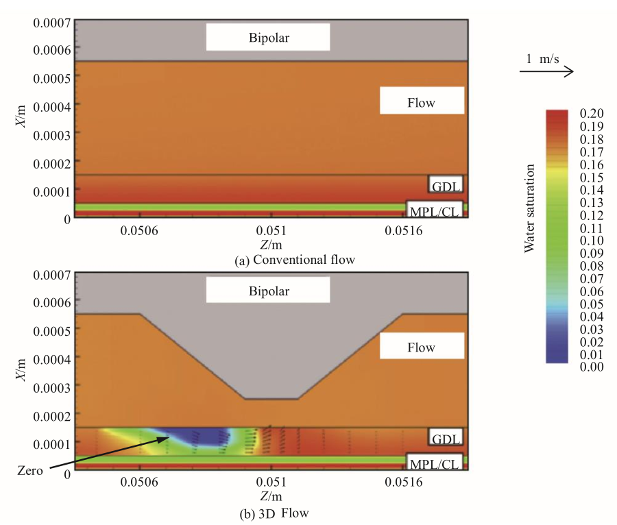
Fig. 5. Simulation results of 3D flow field.
《5 Assembly and consistency of fuel cell stack》
5 Assembly and consistency of fuel cell stack
The assembly and consistency of a fuel cell stack is critical to the performance of the stack. Assembly determines the degree of matching between the components of the stack, and a stack with good consistency can work at high current densities.
A stack is usually assembled on a hydraulic press. Generally, according to the assembly order and positioning method, the MEA is sandwiched with bipolar plates and enclosed with the collector plate and end plate, which are fixed by the fastener to complete the stack. In the assembly of the stack, it is essential to ensure the airtightness of the stack and good contact between the MEA and bipolar plates. In the design stage of the stack, it is important to account for the deformation of the sealing element of the stack and the MEA. During the assembly process, the depth of the bipolar plate within the diffusion layer of the membrane electrode can be quantified by controlling the stack height, while ensuring that the sealing element can reach a predetermined level of deformation [18]. Fig. 6 presents the relative positions of the sealing element, bipolar plates, and MEA in the stack assembly process. The stack height for assembly is h=h1=h2, where h1 is the assembly height that satisfies the MEA depth for the expected lower contact resistance and h2 is the assembly height that meets the requirements for seal deformation. Generally, the depth ratio  for lower contact resistance with the MEA and seal compression ratio
  can be determined by an off-line test, and the seal compression ratio can be adjusted within a certain range (such as 30%–60%) according to the seal structure and materials.

In Equations (1) and (2): is the compression ratio of the seal, is the depth ratio of the bipolar plate to the MEA, bb is the thickness of the bipolar plate, n is the number of cells in a stack, and K is the thickness of other hardware such as the collector plate and the end plate.
《Fig. 6》
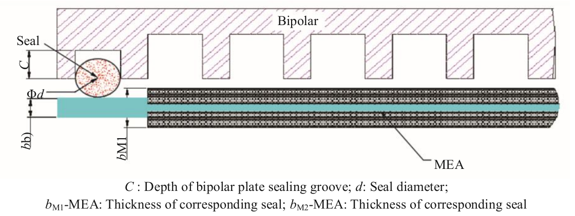
Fig. 6. Relative positions of the seal, bipolar plate, and MEA during the stack assembly process.
While height control can help find the best assembly matching for the stack, the assembly force control method can be used to determine good matching between the components of the stack. The assembly force can be implemented by an assembly machine such as a hydraulic press. As the assembly force increases, the contact between the bipolar plate and the MEA gradually decreases. When the flat area is reached, this is the best assembly force control area (Fig. 7). The relationship between the contact resistance and the assembly force can usually be obtained through the off-line test of a single cell before stack assembly.
《Fig. 7》
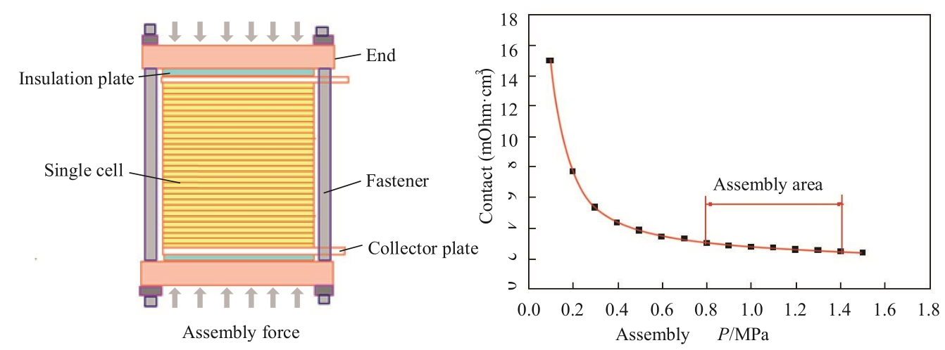
Fig. 7. Schematic diagram of assembly force control and contact resistance of the stack with changes in assembly force.
The consistency of the fuel cell stack is essential to improving the power density of the stack. Consistency indicates the degree to which the voltage of a single cell in the stack deviates from the average voltage of the cells, and a stack with good consistency can achieve synchronous current discharge. If the consistency of a stack is poor, some cells may have low voltages, which can cause reverse polarity when the current is further increased. From the aspect of safety, it is important to avoid reverse polarity during operations. In general, voltage protection should be incorporated in stack systems or bench testing. Therefore, stacks with good consistency can work synchronously at a higher current density to achieve higher power density.
The consistency of a stack is affected by factors such as design, manufacturing, and operation. With regard to stack design, it is necessary to reduce the sensitivity of the structure to possible geometric errors by ensuring the uniformity of fluid distribution. In terms of manufacturing, it is vital to consider the uniformity of materials and control manufacturing precision to ensure the consistency of the initial performance. Regarding the operation of the stack, flooding due to poor layout, reactant starvation, and local hot spots should be avoided to ensure consistent operating performance. In addition, attention should be paid to the problems of uneven temperature and fluid distribution at the edge of the stack, so as to avoid low voltage of a single cell at the edge of the stack.
DICP has been engaged in the research and development of fuel cells for more than 40 years. In recent years, DICP has focused on technologies for high specific power stacks. The research activities cover catalysts, electrode technology and materials, membrane electrodes, flow fields, bipolar plates, stack structure, stack operation management, detection, and control. A high performance enhanced composite proton exchange membrane has been developed to improve fuel cell adaptability for the working conditions of vehicles. Using stainless steel as the substrate metal, DICP has proposed a coating technology with good corrosion-resistant and conductive performance for metallic bipolar plates, increasing the stack’s specific power. In addition, they developed a preparation method of catalyst coated membrane based on electrostatic spraying, greatly improving the power density. From the aspect of stack structure, the influence of the flow field structure and resistance on fluid distribution has been studied through simulations of design, preparation, and operation. DICP explored the dependence of water transfer and distribution on the water generation rate, water transfer coefficient, and electrode/flow field interface energy; analyzed the influence of steady/dynamic load conditions on stack resistance; and ensured good consistency in a stack during operation with a working current density of more than 2.0 A/cm2 . The stack power density developed based on the above technologies and methods can reach 3.0 kW/L (Fig. 8 and Table 3).
《Fig. 8》
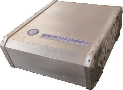
Fig. 8. Fuel cell stack developed by Dalian Institute of Chemical Physics.
《Table 3》
Table 3. Performance of fuel cell stack developed by Dalian Institute of Chemical Physics.

《6 Conclusion》
6 Conclusion
As President Xi Jinping pointed out: “Developing alternative energy vehicles is the only way for China to transform from a big country to a powerful country in the automobile industry.” Given their unique advantages, fuel cell vehicles are becoming the rising star among alternative energy vehicles. However, some bottlenecks need to be resolved in order to achieve large-scale commercialization of these vehicles, such as infrastructure for hydrogen as well as problems concerning policies and regulation. From a technical perspective, further improvements are required to enhance the performance of fuel cells, reduce costs, and improve durability [19]. A fuel cell stack is the core of a fuel cell vehicle, and specific power is an important indicator of the technical capability of a fuel cell stack. Increasing the specific power of the stack can improve the driving power of the vehicle. In addition, a high specific power stack can significantly reduce the cost of the fuel cell hardware for the same power output. High specific power can be achieved by using innovative materials such as highly active catalysts, thin enhanced composite membranes, and conductive and corrosion-resistant bipolar plates. Moreover, it is beneficial to optimize the structure of the stack. For example, the mass transfer polarization with a large current can be improved by using a 3D flow field, the ohmic polarization can be effectively reduced by optimizing the assembly process, and the high-power output of the stack can be ensured by improving the consistency of the stack. These approaches can improve the performance and specific power of the fuel cell stack. It is particularly important for fuel cell commercialization to ensure the high durability and low cost of fuel cell stacks while improving performance and specific power.


 京公网安备 11010502051620号


